1. General Introduction
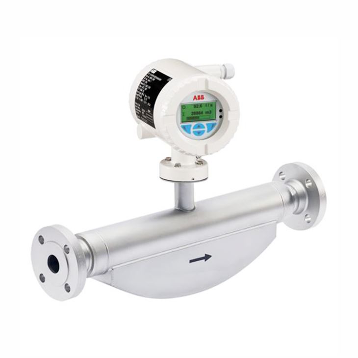
ABB FCB400 Coriolis mass flow meter for high precision measurement of mass flow, volume flow, density, temperature and concentration with low pressure drop. There are two types available, FCB430 with standard accuracy and FCB450 with high accuracy, integrate or remote mount transmitters is optional. For remote mount type, the sensor maximally can meet IP68 with immersion depth five meters under water. For transmitter, both single compartment and dual compartments type are selectable, with standard output protocol Hart, Modbus or Profibus.
2. Measuring range limits
Model | FCB430 | FCB450 |
Measuring accuracy for liquids | ||
Mass flow | 0.4 %, 0.25 % and 0.2 % | 0.1 % and 0.15 % |
Volume flow | 0.4 %, 0.25 % and 0.2 % | 0.15 % and 0.11 % |
Density | 0.01 kg/l | 0.002 kg/l, 0.001 kg/l (optional), 0.0005 kg/l |
Temperature | 1 K | 0.5 K |
Measuring accuracy for gases | 1 % | 0.5 % |
Approved measuring medium | -50 to 160 °C (-58 to 320 °F) | -50 to 205 °C (-58 to 400 °F): |
Process connection | ||
Flange DIN 2501 / EN 1092-1 | DN 10 to 200; PN 40 to PN 160 | |
Flange ASME B16.5 | DN ½ to 8 in.; CL150 to CL1500 | |
JIS flange | DN 10 to 200; JIS 10K to 20K | |
Pipe fitting DIN 11851 | DN 10 to 100 ( to 4 in.) | |
Pipe fitting SMS 1145 | DN 25 to 80 (1 to 3 in.) | |
Tri-clamp DIN 32676 (ISO 2852) | DN 15 to 100 (¼ to 4 in.) | |
Tri-clamp BPE | DN 3/8 to 4 in. | |
Female thread DIN ISO 228 and ASME B 1.20.1 | DN 15; PN 100 | |
Other connections | On request | |
Wetted material | Stainless steel 1.4435 or 1.4404 (AISI 316L), nickel-alloy C4 / C22 (optional) | |
IP rating | Integral mount design: IP 65 / IP 67, NEMA 4X Remote mount design: IP 65 / IP 67 / IP 68 (sensor only, immersion depth: 5 m), NEMA 4X | |
Explosion protection | ATEX / IECEx / cFMus | |
3. Transmitter Specification
Housing | Integral mount design, remote mount design. |
IP rating | IP 65 / IP 67, NEMA 4X |
Cable length | Maximum 200 m (656 ft), remote mount design only |
Power supply | 100 to 240 V AC, 50 / 60 Hz 11 to 30 V DC, nominal voltage: 24 V DC |
Outputs in basic version | Current output: 4 to 20mA active or passive Digital output 1: passive, configurable as pulse, frequency or switch output Digital output 2: passive, configurable as pulse or switch output |
Additional optional outputs | The transmitter has two slots in which plug-in cards can be inserted to provide additional inputs and outputs. The following plug-in cards are available: l Current output (maximum two plug-in cards simultaneously) l Digital output (maximum one plug-in card) l Digital input (maximum one plug-in card) l Modbus or PROFIBUS DP interface (maximum of one plug-in card) l 24 V DC loop power supply for active outputs (maximum one plug-in card) |
External output zero return | Yes |
External totalizer reset | Yes |
Forward / reverse flow metering | Yes |
Counter | Yes |
Communication | HART protocol 7.1 Modbus or Profibus DP (using plug-in card) |
Empty pipe detection | Yes, via configurable density alarm |
Self-monitoring and diagnosis | Yes |
Local indicator | Yes |
Field optimization for flow and density | Yes |
Concentration measurement ‘DensiMass’ | Yes, optional on models FCB450 and FCH450 |
‘FillMass’ fill function | Yes, optional on models FCB450 and FCH450 |
‘VeriMass’ function | Yes, optional |
4. Flow range and meter tube
Nominal diameter | Qmax in kg/h (lb/h) | Meter tube inside diameter |
DN 15 (½ in.) | 0 to 8,000 (0 to 17,637) | 2 x 8 mm (2 x 0.31 in.) |
DN 25 (1 in.) | 0 to 35,000 (0 to 77,162) | 2 x 16 mm (2 x 0.63 in.) |
DN 50 (2 in.) | 0 to 90,000 (0 to 198,416) | 2 x 23.7 mm (2 x 0.93 in.) |
DN 80 (3 in.) | 0 to 250,000 (0 to 551,156) | 2 x 36.62 mm (2 x 1.44 in.) |
DN 100 (4 in.) | 0 to 520,000 (0 to 1,146,404) | 2 x 52.51 mm (2 x 2.07 in.) |
DN 150 (6 in.) | 0 to 860,000 (0 to 1,895,975) | 2 x 68.9 mm (2 x 2.71 in.) |
5. Model selection of FCB430 and FCB450
Main Code | Suffix Codes | Description | |||||||||
FCB430 | CoriolisMaster FCB430 Coriolis Mass Flowmeter | ||||||||||
FCB450 | CoriolisMaster FCB450 Coriolis Mass Flowmeter | ||||||||||
Explosion Protection Certification | Y0 | General Purpose | |||||||||
A2 | ATEX / IECEx (Zone 2 / 22) | ||||||||||
A1 | ATEX / IECEx (Zone 1 / 21) | ||||||||||
F2 | cFMus version Class 1 Div. 2 (Zone 2 / 21) | ||||||||||
F1 | cFMus version Class 1 Div. 1 (Zone 1 / 21) | ||||||||||
Connection Design / Connection Box Material / Cable Glands | Y0 | Integral, defined by Transmitter housing | |||||||||
U1 | Remote / Aluminium / 1 x M20 x 1.5 | ||||||||||
U2 | Remote / Aluminium / 1 x NPT 1/2 in. | ||||||||||
A1 | Remote / Stainless Steel / 1 x M20 x 1.5 | ||||||||||
A2 | Remote / Stainless Steel / 1 x NPT 1/2 in. | ||||||||||
Meter Size / Connection Size | 015E1 | DN 15 (1/2 in.) / DN 10 (3/8 in.) | |||||||||
015R0 | DN 15 (1/2 in.) / DN 15 (1/2 in.) | ||||||||||
015R1 | DN 15 (1/2 in.) / DN 20 (3/4 in.) | ||||||||||
025E1 | DN 25 (1 in.) / DN 20 (3/4 in.) | ||||||||||
025R0 | DN 25 (1 in.) / DN 25 (1 in.) | ||||||||||
025R2 | DN 25 (1 in.) / DN 40 (1-1/2 in.) | ||||||||||
050E1 | DN 50 (2 in.) / DN 40 (1-1/2 in.) | ||||||||||
050R0 | DN 50 (2 in.) / DN 50 (2 in.) | ||||||||||
050R1 | DN 50 (2 in.) / DN 65 (2-1/2 in.) | ||||||||||
080E1 | DN 80 (3 in.) / DN 65 (2-1/2 in.) | ||||||||||
080R0 | DN 80 (3 in.) / DN 80 (3 in.) | ||||||||||
080R1 | DN 80 (3 in.) / DN 100 (4 in.) | ||||||||||
100E1 | DN 100 (4 in.) / DN 80 (3 in.) | ||||||||||
100R0 | DN 100 (4 in.) / DN 100 (4 in.) | ||||||||||
100R2 | DN 100 (4 in.) / DN 150 (6 in.) | ||||||||||
150E2 | DN 150 (6 in.) / DN 100 (4 in.) | ||||||||||
150R0 | DN 150 (6 in.) / DN 150 (6 in.) | ||||||||||
150R2 | DN 150 (6 in.) / DN 200 (8 in.) | ||||||||||
Process Connection Type | D2 | Flanges DIN PN 16 | |||||||||
D4 | Flanges DIN PN 40 | ||||||||||
D5 | Flanges DIN PN 63 | ||||||||||
D6 | Flanges DIN PN 100 | ||||||||||
S5 | Flanges EN 1092-1 PN 40, NAMUR length (DN 15, DN 25, DN 50) | ||||||||||
S6 | Flanges with groove PN40 EN1092-10-D | ||||||||||
S7 | Flanges EN 1092-1 PN 16, NAMUR length (DN 100, DN 150) | ||||||||||
A1 | Flanges ANSI / ASME B16.5 Class 150 | ||||||||||
A3 | Flanges ANSI / ASME B16.5 Class 300 | ||||||||||
A6 | Flanges ANSI / ASME B16.5 Class 600 | ||||||||||
A7 | Flanges ANSI / ASME B16.5 Class 900 (p-t rating Cl 600) | ||||||||||
A8 | Flanges ANSI / ASME B16.5 Class 1500 (p-t rating Cl 600) | ||||||||||
J1 | Flanges JIS 10K | ||||||||||
J3 | Flanges JIS 20K | ||||||||||
K1 | Sanitary Couplings SMS1145 for pipes acc. DIN11866 Series A | ||||||||||
T1 | Tri-Clamp acc. DIN 32676 | ||||||||||
T3 | Tri-Clamp acc. BPE | ||||||||||
F1 | Food industry fittings acc. DIN 11851 | ||||||||||
N5 | Female NPT thread | ||||||||||
M5 | Female G thread | ||||||||||
Z9 | Others | ||||||||||
Material of Wetted Parts | A1 | Stainless steel | |||||||||
C1 | Ni-Alloy | ||||||||||
Flow Calibration | A | Flow forward +/- 0.40 % of flow rate, Gas 1 % of flow rate | |||||||||
B | Flow forward +/- 0.25 % of flow rate, Gas 1 % of flow rate | ||||||||||
E | Flow forward +/- 0.2 % of flow rate, Gas 1 % of flow rate | ||||||||||
C | Forward +/-0.15% of flow rate, Gas 0.5 % of flow rate | ||||||||||
D | Forward +/-0.10% of flow rate, Gas 0.5 % of flow rate | ||||||||||
J | Flow forward / reverse +/- 0.40 % of flow rate, Gas 1 % of flow rate | ||||||||||
K | Flow forward / reverse +/- 0.25 % of flow rate, Gas 1 % of flow rate | ||||||||||
N | Flow forward / reverse +/- 0.20 % of flow rate, Gas 1 % of flow rate | ||||||||||
L | Flow forward / reverse +/- 0.15 % of flow rate, Gas 0.5 % of flow rate | ||||||||||
M | Flow forward / reverse +/- 0.10 % of flow rate, Gas 0.5 % of flow rate | ||||||||||
Z | Others | ||||||||||
Density Calibration | 1 | Density 10 g/l | |||||||||
3 | Density 2 g/l | ||||||||||
4 | Density 1 g/l | ||||||||||
5 | Density 0.5 g/l | ||||||||||
9 | Others | ||||||||||
Connection Design / Transmitter Housing Type / Transmitter Housing Material / Cable Glands | S1 | Integral / Single-compartment / Aluminum / 3 x M20 x 1,5 | |||||||||
S2 | Integral / Single-compartment / Aluminum / 3 x NPT 1/2 in. | ||||||||||
D1 | Integral / Dual compartment / Aluminum / 3 x M20 x 1.5 | ||||||||||
D2 | Integral / Dual compartment / Aluminum / 3 x NPT 1/2 in. | ||||||||||
D5 | Integral / Dual compartment / Aluminum / 3 x NPT 1/2 in. (Exd, XP) | ||||||||||
D6 | Integral / Dual compartment / Aluminum / 3 x M20 x 1.5 (Exd, XP) | ||||||||||
Y0 | Remote / Not specified | ||||||||||
Z9 | Others | ||||||||||
Outputs | G0 | Current output 1 (active or passive), digital output 1 & 2 (passive), HART | |||||||||
G1 | Current output 1 (active or passive), digital output 1 & 2 (passive), 24 V DC transmitter loop power supply, HART | ||||||||||
G2 | Current output 1 (active or passive), digital output 1 & 2 (passive), current output 2 (passive), HART | ||||||||||
G3 | Current output 1 (active or passive), digital output 1 & 2 (passive), current output 2 (passive), current output 3 (passive), HART | ||||||||||
G4 | Current output 1 (active or passive), digitial output 1 & 2 (passive), current output 2 (passive), 24 V DC transmitter loop power supply, HART | ||||||||||
M1 | Current output 1 (active or passive), digital output 1 & 2 (passive), HART, MODBUS | ||||||||||
D1 | Current output 1 (active or passive), digital output 1 & 2 (passive), HART, PROFIBUS DP | ||||||||||
Y0 | Without | ||||||||||
Power Supply | A | 100 ... 230 V AC | |||||||||
C | 11 ... 30 V DC | ||||||||||
Y | Without | ||||||||||
Optional codes | /Optional codes | ||||||||||
6. Model selection of transmitter FCT430 and FCT450
Main Code | Suffix Codes | Description | |||
FCT430 | CoriolisMaster FCT430 Coriolis Mass Flowmeter Transmitter | ||||
FCT450 | CoriolisMaster FCT430 Coriolis Mass Flowmeter Transmitter | ||||
Explosion Protection Certification | Y0 | General Purpose | |||
A2 | ATEX / IECEx (Zone 2 / 22) | ||||
A1 | ATEX / IECEx (Zone 1 / 21) | ||||
F2 | cFMus version Class 1 Div. 2 (Zone 2 / 21) | ||||
F1 | cFMus version Class 1 Div. 1 (Zone 1 / 21) | ||||
Connection Design / Transmitter Housing Type / Transmitter Housing Material / Cable Glands | W1 | Remote / Single-compartment / Aluminum / 4 x M20 x 1.5 | |||
W2 | Remote / Single-compartment / Aluminum / 4 x NPT 1/2 in. | ||||
R1 | Remote / Dual compartment, wall mounted / Aluminum / 4 x M20 x 1.5 | ||||
R2 | Remote / Dual compartment, wall mounted / Aluminum / 4 x NPT 1/2 in. | ||||
R5 | Remote / Dual compartment, wall mounted / Aluminum / 4 x M20 x 1.5 (Exd, XP) | ||||
R6 | Remote / Dual compartment, wall mounted / Aluminum / 4 x NPT 1/2 in. (Exd, XP) | ||||
Z9 | Others | ||||
Outputs | G0 | Current output 1 (active or passive), digital output 1 & 2 (passive), HART | |||
G1 | Current output 1 (active or passive), digital output 1 & 2 (passive), 24 V DC transmitter loop power supply, HART | ||||
G2 | Current output 1 (active or passive), digital output 1 & 2 (passive), current output 2 (passive), HART | ||||
G3 | Current output 1 (active or passive), digital output 1 & 2 (passive), current output 2 (passive), current output 3 (passive), HART | ||||
G4 | Current output 1 (active or passive), digital output 1 & 2 (passive), current output 2 (passive), 24 V DC transmitter loop power supply, HART | ||||
M1 | Current output 1 (active or passive), digital output 1 & 2 (passive), HART, MODBUS | ||||
D1 | Current output 1 (active or passive), digital output 1 & 2 (passive), HART, PROFIBUS DP | ||||
Z9 | Others | ||||
Power Supply | A | 100 ... 230 V AC | |||
C | 11 ... 30 V DC | ||||
Optional codes | /Optional codes | ||||
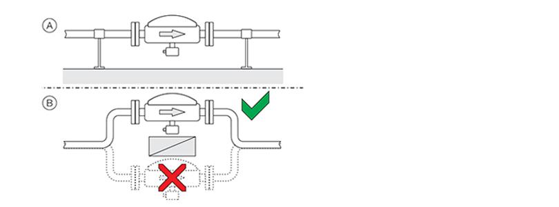
7. Location and position of installation
◆ Horizontal mounting of liquid measuring medium
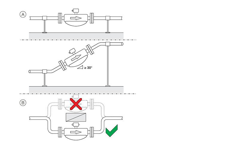
◆ Horizontal mounting of gas measuring medium