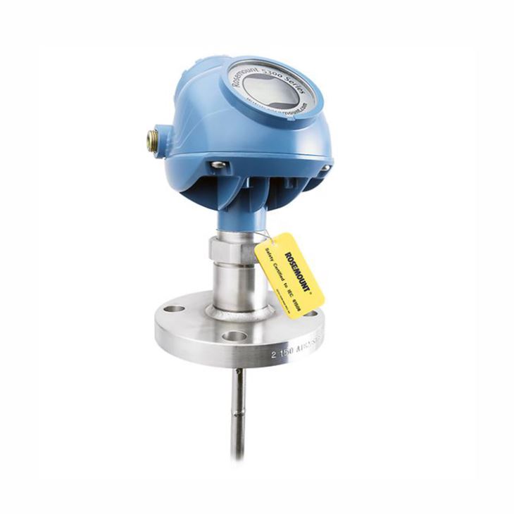
1. General Introduction
Rosemount 5300 Guided Wave Radar Level Transmitter supply reliable and safe level and interface measurements of liquids, slurries, and solids. It has a robust construction and features powerful built-in diagnostics and certified to IEC 61508 for SIL2 applications, which is suitable for small tanks, difficult tank geometry, internal obstacles, and unaffected by the mechanical design of chambers.
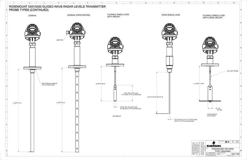
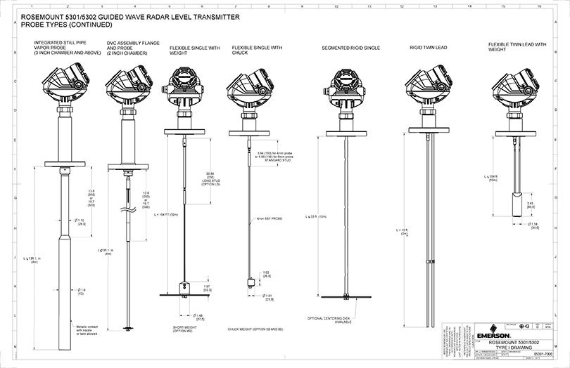
2. Minimum and maximum probe length
Probe type | Probe length |
Flexible single lead | 3.3 to 164 ft. (1 to 50 m) |
Rigid single lead (0.3 in./8 mm) | 1.3 to 9.8 ft. (0.4 to 3 m) |
Rigid single lead (0.5 in./13 mm) | 1.3 to 19.7 ft. (0.4 to 6 m) |
Segmented rigid single lead | 1.3 to 32.8 ft. (0.4 to 10 m) |
Flexible twin lead | 3.3 to 164 ft. (1 to 50 m) |
Rigid twin lead | 1.3 to 9.8 ft. (0.4 to 3 m) |
Coaxial | 1.3 to 19.7 ft. (0.4 to 6 m) |
Large coaxial | 1.0 to 19.7 ft. (0.3 to 6 m) |
3. Basic code selection of 5300 Guided Wave Radar Level Transmitter
5301 | Guided Wave Radar Liquid Level or Interface Transmitter | |||||||||||
5302 | Guided Wave Radar Liquid Level and Interface Transmitter | |||||||||||
Signal output | H | 4-20mA with HART communication | ||||||||||
F | FOUNDATION Fieldbus | |||||||||||
M | RS-485 with Modbus communication | |||||||||||
U | Rosemount 2410 Tank Hub Connectivity | |||||||||||
Housing material | A | Polyurethane-covered Aluminum | ||||||||||
S | Stainless Steel, Grade CF8M (ASTM A743) | |||||||||||
Conduit/cable threads | 1 | 1/2-14 NPT | ||||||||||
2 | M20 x 1.5 adapter | |||||||||||
4 | 2 pcs M20 x 1.5 adapter | |||||||||||
G | Metal cable gland (1/2-14 NPT) | |||||||||||
E | M12, 4-pin, male connector | |||||||||||
M | A size Mini, 4-pin, male connector | |||||||||||
Oper. temperature and pressure | S | -1 to 40 bar @ 150℃ | ||||||||||
H | 345 bar @ 38℃ and 203 bar @ 400℃ | |||||||||||
P | 345 bar @ 38℃ and 228.9 bar @ 250℃ | |||||||||||
C | 345 bar @ -196℃ and 243 bar @ 200℃ | |||||||||||
Material of construction | 1 | 316/316L/EN 1.4404 | ||||||||||
2 | Alloy C-276 | |||||||||||
3 | Alloy 400 | |||||||||||
7 | PTFE covered probe and flange | |||||||||||
8 | PTFE covered probe | |||||||||||
H | Alloy C-276 process connection, flange, and probe | |||||||||||
D | Duplex 2205 process connection, flange, and probe | |||||||||||
Sealing, O-ring material | N | None | ||||||||||
V | Viton Fluoroelastomer | |||||||||||
E | Ethylene Propylene (EPDM) | |||||||||||
K | Kalrez 6375 Perfluoroelastomer | |||||||||||
B | Nitrile Butadiene (NBR) | |||||||||||
L | Low temperature Viton Fluoroelastomer | |||||||||||
F | Fluorsilicone (FVMQ) | |||||||||||
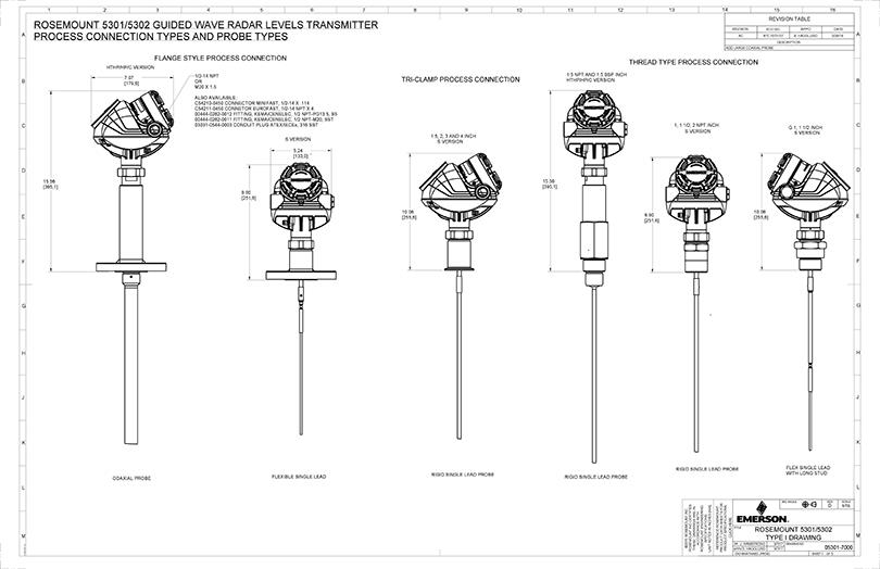
Probe type and Process connections | 3B | Coaxial,Flange & Thread | ||||||||||
3C | Large coaxial,Flange & Thread | |||||||||||
3V | Integrated Still Pipe Vapor Probe, Flange | |||||||||||
4A | Rigid Single Lead (8 mm), Flange & Thread& Tri-Clamp | |||||||||||
4B | Rigid Single Lead (13 mm), Flange & Thread& Tri-Clamp | |||||||||||
4U | Single Rigid Vapor Probe, Flange & Thread | |||||||||||
5A | Flexible Single Lead with weight, Flange & Thread& Tri-Clamp | |||||||||||
5B | Flexible Single Lead with chuck, Flange & Thread& Tri-Clamp | |||||||||||
1A | Rigid Twin Lead, Flange & Thread | |||||||||||
2A | Flexible Twin Lead with weight, Flange & Thread | |||||||||||
3A | Coaxial, Flange & Thread | |||||||||||
4S | Segmented Rigid Single Lead (13mm), Flange & Thread& Tri-Clamp | |||||||||||
Probe length units | E | English (feet, in.) | ||||||||||
M | Metric (meters, centimeters) | |||||||||||
Total probe length (feet/m) | XXX | 0-164 ft. or 0-50 m | ||||||||||
Total probe length (in./cm) | XX | 0-11 in. or 0-99 cm | ||||||||||
Process connection | AA | 2-in. Class 150, RF | ||||||||||
AB | 2-in. Class 300, RF | |||||||||||
AC | 2-in. Class 600, RF | |||||||||||
AD | 2-in. Class 900, RF | |||||||||||
BA | 3-in. Class 150, RF | |||||||||||
BB | 3-in. Class 300, RF | |||||||||||
BC | 3-in. Class 600, RF | |||||||||||
BD | 3-in. Class 900, RF | |||||||||||
CA | 4-in. Class 150, RF | |||||||||||
CB | 4-in. Class 300, RF | |||||||||||
CC | 4-in. Class 600, RF | |||||||||||
CD | 4-in. Class 900, RF | |||||||||||
AE | 2-in. Class 1500, RF | |||||||||||
AF | 2-in. Class 2500, RF | |||||||||||
AI | 2-in. Class 600, RTJ | |||||||||||
AJ | 2-in. Class 900, RTJ | |||||||||||
AK | 2-in. Class 1500, RTJ | |||||||||||
BE | 3-in. Class 1500, RF | |||||||||||
BF | 3-in. Class 2500, RF | |||||||||||
BI | 3-in. Class 600, RTJ | |||||||||||
BJ | 3-in. Class 900, RTJ | |||||||||||
BK | 3-in. Class 1500, RTJ | |||||||||||
CE | 4-in. Class 1500, RF | |||||||||||
CF | 4-in. Class 2500, RF | |||||||||||
CI | 4-in. Class 600, RTJ | |||||||||||
CJ | 4-in. Class 900, RTJ | |||||||||||
CK | 4-in. Class 1500, RTJ | |||||||||||
DA | 6-in. Class 150, RF | |||||||||||
Optional codes | Optional codes [ As per table below] | |||||||||||
4. Typical mounting & dimensions for 5300 Guided Wave Radar Level Transmitter