1. General introduction
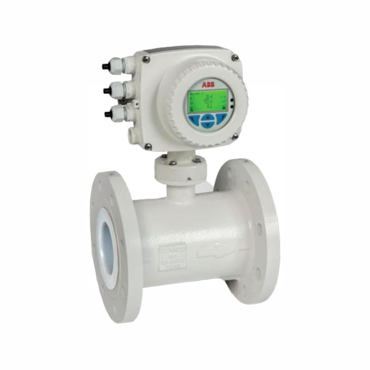
ABB FEP630 – The first choice for all industrial applications.
Advanced features and functionality that enable you to operate more efficiently, reduce costs and increase profitably.
1.1 Real-time Diagnostic keep your process up and running
- Detecting critical process conditions at an early stage reduce unscheduled downtime and maintenance
- Clear text messages simplify troubleshooting
1.2 In-built Noise/Grounding Check
- Verify the installation is correct from day one
- Checks for proper grounding which is fundamental to an accurate flow measurement
1.3 In-built Verification for highest confidence in your flow measurement
- Checking for sensor and transmitter integrity
- No need to remove the flowmeter from the process
1.4 Best in class filtering technology
- For a most stable flow signal
- Helping to operate your process at peak level performance
1.5 Simplicity of Operation
- Automatic self-configuration sequence
-Incredibly easy to work with
1.6 Backwards Compatibility
- Saves your investment in ABB flowmetering
2. Compare Table of FEP631 FEP632 and FET632
Model | FEP631 | FEP632 | FET632 |
Housing | Integral mount design | remote mount design | |
Measuring accuracy for liquids | 0.4 % of measured value, option for 0.3 % and 0.2 % of measured value | ||
Permissible measuring medium temperature Tmedium | Standard: -25 ... 130 ºC(-13 ... 266 ºF) Option: -25 … 180 ºC(-13 … 356 ºF) | ||
Minimum conductivity | > 5 μS/cm (20 μS/cm for demineralized water) | ||
Nominal pressure rating | PN 10 … 40, PN 63, PN 100; ASME CL 150, CL 300, CL 600; JIS 10K | ||
Nominal diameter | DN 3 ... 2000 (1/10“ ... 80“) | ||
Process connection | Flange according to DIN, ASME, JIS | ||
Process connection material | Steel, cast iron, stainless steel | ||
Liner material | Hard rubber (DN 25 ... 2000), soft rubber (DN 50 ... 2000), PTFE (DN 10 ... 600), PFA (DN 3 ... 200), ETFE (DN 25 ... 600), Ceramic Carbide (DN 25 … 1000), Linatex (DN 50 … 600) | ||
Electrode material | Stainless steel, Hastelloy B, Hastelloy C, Platinum-Iridium, Tantalum, Titanium, Double layer, Tungsten carbide | ||
IP rating | IP 65 / IP 67 / NEMA 4X | IP 65 / IP 67 / IP 68 (sensor only) / NEMA 4X | |
Pressure Equipment Directive 2014/68/EU | Conformity assessment in accordance with category III, fluid group 1 | - | |
CRN (Canadian Reg.Number) | On request | - | |
Explosion protection (In preparation) | ATEX / IECEx Zone 1, 2, 21, 22 FM / cFM Cl 1 Div 1 (≤ DN 300), Cl 1 Div 2 | ||
Cable length | - | Maximum 200 m (656 ft), remote mount design only | |
Power supply | 100 ... 240 V AC (-15 / +10 %) 50 / 60 Hz, 16,8 ... 30 V DC | ||
Outputs | Current output: 4 … 20 mA, active or passive (configurable on site) Digital output 1: passive, configurable as pulse, frequency or switch output Digital output 2: passive, configurable as pulse or switch output | ||
Additional outputs | The transmitter has two slots in the plug-in cards that can be used to extend the outputs. The following plug-in cards are available: Current output (passive) Digital output (passive) Digital input (passive) 24 V DC power supply for active outputs | - | The transmitter has two slots in the plug-in cards that can be used to extend the outputs. The following plug-in cards are available: Current output (passive) Digital output (passive) Digital input (passive) 24 V DC power supply for active outputs |
Communication | Standard: HART 7.1 Option: PROFIBUS DP (in preparation) / Modbus (in preparation) | - | Standard: HART 7.1 Option: PROFIBUS DP (in preparation) / Modbus (in preparation) |
3. Measuring Range Table
Nominal Diameter | Min. flow range end value 0.02×QmaxDN (≈0.2m/s) | QmaxDN 0…≈10m/s | Max. flow range end value 2×QmaxDN (≈20m/s) | |
DN | Inch | |||
3 | 1/10 | 0.08 l/min (0.02 US gal/min) | 4 l/min (1.06 US gal/min) | 8 l/min (2.11 US gal/min) |
4 | 5/32 | 0.16 l/min (0.04 US gal/min) | 8 l/min (2.11 US gal/min) | 16 l/min (4.23 US gal/min) |
6 | 1/4 | 0.4 l/min (0.11 US gal/min) | 20 l/min (5.28 US gal/min) | 40 l/min (10.57 US gal/min) |
8 | 5/16 | 0.6 l/min (0.16 US gal/min) | 30 l/min (7.93 US gal/min) | 60 l/min (15.85 US gal/min) |
10 | 3/8 | 0.9 l/min (0.24 US gal/min) | 45 l/min (11.9 US gal/min) | 90 l/min (23.78 US gal/min) |
15 | 1/2 | 2 l/min (0.53 US gal/min) | 100 l/min (26.4 US gal/min) | 200 l/min (52.8 US gal/min) |
20 | 3/4 | 3 l/min (0.79 US gal/min) | 150 l/min (39.6 US gal/min) | 300 l/min (79.3 US gal/min) |
25 | 1 | 4 l/min (1.06 US gal/min) | 200 l/min (52.8 US gal/min) | 400 l/min (106 US gal/min) |
32 | 1 1/4 | 8 l/min (2.11 US gal/min) | 400 l/min (106 US gal/min) | 800 l/min (211 US gal/min) |
40 | 1 1/2 | 12 l/min (3.17 US gal/min) | 600 l/min (159 US gal/min) | 1200 l/min (317 US gal/min) |
50 | 2 | 1.2 m3/h (5.28 US gal/min) | 60 m3/h (264 US gal/min) | 120 m3/h (528 US gal/min) |
65 | 2 1/2 | 2.4 m3/h (10.57 US gal/min) | 120 m3/h (528 US gal/min) | 240 m3/h (1057 US gal/min) |
80 | 3 | 3.6 m3/h (15.9 US gal/min) | 180 m3/h (793 US gal/min) | 360 m3/h (1585 US gal/min) |
100 | 4 | 4.8 m3/h (21.1 US gal/min) | 240 m3/h (1057 US gal/min) | 480 m3/h (2113 US gal/min) |
125 | 5 | 8.4 m3/h (37 US gal/min) | 420 m3/h (1849 US gal/min) | 840 m3/h (3698 US gal/min) |
150 | 6 | 12 m3/h (52.8 US gal/min) | 600 m3/h (2642 US gal/min) | 1200 m3/h (5283 US gal/min) |
200 | 8 | 21.6 m3/h (95.1 US gal/min) | 1080 m3/h (4755 US gal/min) | 2160 m3/h (9510 US gal/min) |
250 | 10 | 36 m3/h (159 US gal/min) | 1800 m3/h (7925 US gal/min) | 3600 m3/h (15850 US gal/min) |
300 | 12 | 48 m3/h (211 US gal/min) | 2400 m3/h (10567 US gal/min) | 4800 m3/h (21134 US gal/min) |
350 | 14 | 66 m3/h (291 US gal/min) | 3300 m3/h (14529 US gal/min) | 6600 m3/h (29059 US gal/min) |
400 | 16 | 90 m3/h (396 US gal/min) | 4500 m3/h (19813 US gal/min) | 9000 m3/h (39626 US gal/min) |
450 | 18 | 120 m3/h (528 US gal/min) | 6000 m3/h (26417 US gal/min) | 12000 m3/h (52834 US gal/min) |
500 | 20 | 132 m3/h (581 US gal/min) | 6600 m3/h (29059 US gal/min) | 13200 m3/h (58117 US gal/min) |
600 | 24 | 192 m3/h (845 US gal/min) | 9600 m3/h (42268 US gal/min) | 19200 m3/h (84535 US gal/min) |
700 | 28 | 264 m3/h (1162 US gal/min) | 13200 m3/h (58118 US gal/min) | 26400 m3/h (116236 US gal/min) |
760 | 30 | 312 m3/h (1374 US gal/min) | 15600 m3/h (68685 US gal/min) | 31200 m3/h (137369 US gal/min) |
800 | 32 | 360 m3/h (1585 US gal/min) | 18000 m3/h (79252 US gal/min) | 36000 m3/h (158503 US gal/min) |
900 | 36 | 480 m3/h (2113 US gal/min) | 24000 m3/h (105669 US gal/min) | 48000 m3/h (211337 US gal/min) |
1000 | 40 | 540 m3/h (2378 US gal/min) | 27000 m3/h (118877 US gal/min) | 54000 m3/h (237754 US gal/min) |
1050 | 42 | 616 m3/h (2712 US gal/min) | 30800 m3/h (135608 US gal/min) | 61600 m3/h (271217 US gal/min) |
1100 | 44 | 660 m3/h (3038 US gal/min) | 33000 m3/h (151899 US gal/min) | 66000 m3/h (290589 US gal/min) |
1200 | 48 | 840 m3/h (3698 US gal/min) | 42000 m3/h (184920 US gal/min) | 84000 m3/h (369841 US gal/min) |
1400 | 54 | 1080 m3/h (4755 US gal/min) | 54000 m3/h (237755 US gal/min) | 108000 m3/h (475510 US gal/min) |
1500 | 60 | 1260 m3/h (5548 US gal/min) | 63000 m3/h (277381 US gal/min) | 126000 m3/h (554761 US gal/min) |
1600 | 66 | 1440 m3/h (6340 US gal/min) | 72000 m3/h (317006 US gal/min) | 144000 m3/h (634013 US gal/min) |
1800 | 72 | 1800 m3/h (7925 US gal/min) | 90000 m3/h (396258 US gal/min) | 180000 m3/h (792516 US gal/min) |
2000 | 80 | 2280 m3/h (10039 US gal/min) | 114000 m3/h (501927 US gal/min) | 228000 m3/h (1003853 US gal/min) |
4. Temperature Data of Integral Mount Design
Liner | Flange material | Ambient temperature | Measuring medium temperature | ||
Minimum | Maximum | Minimum | Maximum | ||
Standard | |||||
Hard rubber | Steel | -10 ºC (14 ºF) | 60 ºC(140 ºF) | -10 ºC(14 ºF) -5 ºC(23 ºF) | 85 ºC(185 ºF) 80 ºC(176 ºF) |
Hard rubber | Stainless steel | -15 ºC(5 ºF) | 60 ºC(140 ºF) | -15 ºC(5 ºF) -5 ºC(23 ºF) | 85 ºC(185 ºF) 80 ºC(176 ºF) |
Soft rubber | Steel | -10 ºC(14 ºF) | 60 ºC(140 ºF) | -10 ºC(14 ºF) | 60 ºC(140 ºF) |
Soft rubber | Stainless steel | -15 ºC(5 ºF) | 60 ºC(140 ºF) | -15 ºC(5 ºF) | 60 ºC(140 ºF) |
PTFE | Steel | -10 ºC(14 ºF) | 60 ºC(140 ºF) 45 ºC(113 ºF) | -10 ºC(14 ºF) | 90 ºC(194 ºF) 130 ºC(266 ºF) |
PTFE | Stainless steel | -20 ºC(-4 ºF) -40 ºC(-40 ºF) | 60 ºC(140 ºF) 45 ºC(113 ºF) | -25 ºC(-13 ºF) | 90 ºC(194 ºF) 130 ºC(266 ºF) |
PFA | Steel | -10 ºC(14 ºF) | 60 ºC(140 ºF) 45 ºC(113 ºF) | -10 ºC(14 ºF) | 90 ºC(194 ºF) 130 ºC(266 ºF) |
PFA | Stainless steel | -20 ºC(-4 ºF) -40 ºC(-40 ºF) | 60 ºC(140 ºF) 45 ºC(113 ºF) | -25 ºC(-13 ºF) | 90 ºC(194 ºF) 130 ºC(266 ºF) |
Thick PTFE | Steel | -10 ºC(14 ºF) | 60 ºC(140 ºF) 45 ºC(113 ºF) | -10 ºC(14 ºF) | 90 ºC(194 ºF) 130 ºC(266 ºF) |
Thick PTFE | Stainless steel | -20 ºC(-4 ºF) -40 ºC(-40 ºF) | 60 ºC(140 ºF) 45 ºC(113 ºF) | -25 ºC(-13 ºF) | 90 ºC(194 ºF) 130 ºC(266 ºF) |
ETFE | Steel | -10 ºC(14 ºF) | 60 ºC(140 ºF) 45 ºC(113 ºF) | -10 ºC(14 ºF) | 90 ºC(194 ºF) 130 ºC(266 ºF) |
ETFE | Stainless steel | -20 ºC(-4 ºF) -40 ºC(-40 ºF) | 60 ºC(140 ºF) 45 ºC(113 ºF) | -25 ºC(-13 ºF) | 90 ºC(194 ºF) 130 ºC(266 ºF) |
Linatex | Steel | -10 ºC(14 ºF) | 60 ºC(140 ºF) | -10 ºC(14 ºF) | 70 ºC(158 ºF) |
Linatex | Stainless steel | -20 ºC(-4 ºF) | 60 ºC(140 ºF) | -20 ºC(-4 ºF) | 70 ºC(158 ºF) |
Ceramic carbide | Steel | -10 ºC(14 ºF) | 60 ºC(140 ºF) | -10 ºC(14 ºF) | 80 ºC(176 ºF) |
Ceramic carbide | Stainless steel | -20 ºC(-4 ºF) | 60 ºC(140 ºF) | -20 ºC(-4 ºF) | 80 ºC(176 ºF) |
High-temperature | |||||
PFA | Steel | -10 ºC(14 ºF) | 60 ºC(140 ºF) | -10 ºC(14 ºF) | 180 ºC(356 ºF) |
PFA | Stainless steel | -20 ºC(-4 ºF) -40 ºC(-40 ºF) | 60 ºC(140 ºF) | -20 ºC(-4 ºF) | 180 ºC(356 ºF) |
Thick PTFE | Steel | -10 ºC(14 ºF) | 60 ºC(140 ºF) | -10 ºC(14 ºF) | 180 ºC(356 ºF) |
Thick PTFE | Stainless steel | -20 ºC(-4 ºF) -40 ºC(-40 ºF) | 60 ºC(140 ºF) | -20 ºC(-4 ºF) | 180 ºC(356 ºF) |
ETFE | Steel | -10 ºC(14 ºF) | 60 ºC(140 ºF) | -10 ºC(14 ºF) | 130 ºC(266 ºF) |
ETFE | Stainless steel | -20 ºC(-4 ºF) -40 ºC(-40 ºF) | 60 ºC(140 ºF) | -20 ºC(-4 ºF) | 130 ºC(266 ºF) |
5. Temperature Data of Remote Mount Design
Liner | Flange material | Ambient temperature | Measuring medium temperature | ||
Minimum | Maximum | Minimum | Maximum | ||
Standard | |||||
Hard rubber | Steel | -10 ºC(14 ºF) | 60 ºC(140 ºF) | -10 ºC(14 ºF) -5 ºC(23 ºF) | 85 ºC(185 ºF) 80 ºC(176 ºF) |
Hard rubber | Stainless steel | -15 ºC(5 ºF) | 60 ºC(140 ºF) | -15 ºC(5 ºF) -5 ºC(23 ºF) | 85 ºC(185 ºF) 80 ºC(176 ºF) |
Soft rubber | Steel | -10 ºC(14 ºF) | 60 ºC(140 ºF) | -10 ºC(14 ºF) | 60 ºC(140 ºF) |
Soft rubber | Stainless steel | -15 ºC(5 ºF) | 60 ºC(140 ºF) | -15 ºC(5 ºF) | 60 ºC(140 ºF) |
PTFE | Steel | -10 ºC(14 ºF) | 60 ºC(140 ºF) 45 ºC(113 ºF) | -10 ºC(14 ºF) | 130 ºC(266 ºF) |
PTFE | Stainless steel | -25 ºC(-13 ºF) -40 ºC(-40 ºF) | 60 ºC(140 ºF) | -25 ºC(-13 ºF) | 130 ºC(266 ºF) |
PFA | Steel | -10 ºC(14 ºF) | 60 ºC(140 ºF) | -10 ºC(14 ºF) | 130 ºC(266 ºF) |
PFA | Stainless steel | -25 ºC(-13 ºF) -40 ºC(-40 ºF) | 60 ºC(140 ºF) | -25 ºC(-13 ºF) | 130 ºC(266 ºF) |
Thick PTFE | Steel | -10 ºC(14 ºF) | 60 ºC(140 ºF) | -10 ºC(14 ºF) | 130 ºC(266 ºF) |
Thick PTFE | Stainless steel | -25 ºC(-13 ºF) -40 ºC(-40 ºF) | 60 ºC(140 ºF) | -25 ºC(-13 ºF) | 130 ºC(266 ºF) |
ETFE | Steel | -10 ºC(14 ºF) | 60 ºC(140 ºF) | -10 ºC(14 ºF) | 130 ºC(266 ºF) |
ETFE | Stainless steel | -25 ºC(-13 ºF) | 60 ºC(140 ºF) | -25 ºC(-13 ºF) | 130 ºC(266 ºF) |
Linatex | Steel | -10 ºC(14 ºF) | 60 ºC(140 ºF) | -10 ºC(14 ºF) | 70 ºC(158 ºF) |
Linatex | Stainless steel | -20 ºC(-4 ºF) | 60 ºC(140 ºF) | -20 ºC(-4 ºF) | 70 ºC(158 ºF) |
Ceramic carbide | Steel | -10 ºC(14 ºF) | 60 ºC(140 ºF) | -10 ºC(14 ºF) | 80 ºC(176 ºF) |
Ceramic carbide | Stainless steel | -25 ºC(-13 ºF) | 60 ºC(140 ºF) | -20 ºC(-4 ºF) | 80 ºC(176 ºF) |
High-temperature | |||||
PFA | Steel | -10 ºC (14 ºF) | 60 ºC(140 ºF) | -10 ºC(14 ºF) | 180 ºC(356 ºF) |
PFA | Stainless steel | -25 ºC(-13 ºF) -40 ºC(-40 ºF) | 60 ºC(140 ºF) | -25 ºC(-13 ºF) | 180 ºC(356 ºF) |
Thick PTFE | Steel | -10 ºC(14 ºF) | 60 ºC(140 ºF) | -10 ºC(14 ºF) | 180 ºC(356 ºF) |
Thick PTFE | Stainless steel | -25 ºC(-13 ºF) -40 ºC(-40 ºF) | 60 ºC(140 ºF) | -25 ºC(-13 ºF) | 180 ºC(356 ºF) |
ETFE | Steel | -10 ºC(14 ºF) | 60 ºC(140 ºF) | -10 ºC(14 ºF) | 130 ºC(266 ºF) |
ETFE | Stainless steel | -25 ºC(-13 ºF) -40 ºC(-40 ºF) | 60 ºC(140 ºF) | -25 ºC(-13 ºF) | 130 ºC(266 ºF) |
6. Basic Code Selection of FEP 631
Main Code | Suffix Codes | Description | ||||||||||||||
FEP631 | Always FEP631 | |||||||||||||||
Explosion Protection Certification | Y0 | Without | ||||||||||||||
Housing Type / Housing Material / Thread for Cable Glands | S1 | Single compartment / Aluminium / M20 x 1.5 | ||||||||||||||
S2 | Single compartment / Aluminium / NPT 1/2 in. | |||||||||||||||
D1 | Dual compartment / Aluminium / M20 x 1.5 | |||||||||||||||
D2 | Dual compartment / Aluminium / NPT 1/2 in. | |||||||||||||||
Meter size | 0003 | DN 3 (1/10 in.) | ||||||||||||||
0004 | DN 4 (5/32 in) | |||||||||||||||
0005 | DN 6 (1/4 in) | |||||||||||||||
0008 | DN 8 (5/16in) | |||||||||||||||
0010 | DN 10 (3/8 in.) | |||||||||||||||
0015 | DN 15 (1/2 in.) | |||||||||||||||
0020 | DN 20 (3/4 in.) | |||||||||||||||
0025 | DN 25 (1 in.) | |||||||||||||||
0032 | DN 32 (1-1/4 in.) | |||||||||||||||
0040 | DN 40 (1-1/2 in.) | |||||||||||||||
0050 | DN 50 (2 in.) | |||||||||||||||
0065 | DN 65 (2-1/2 in.) | |||||||||||||||
0080 | DN 80 (3 in.) | |||||||||||||||
0100 | DN 100 (4 in.) | |||||||||||||||
0125 | DN 125 (5 in.) | |||||||||||||||
0150 | DN 150 (6 in.) | |||||||||||||||
0200 | DN 200 (8 in.) | |||||||||||||||
0250 | DN 250 (10 in.) | |||||||||||||||
0300 | DN 300 (12 in.) | |||||||||||||||
0350 | DN 350 (1/14in.) | |||||||||||||||
0400 | DN 400 (16 in.) | |||||||||||||||
0450 | DN 450 (18 in.) | |||||||||||||||
0500 | DN 500 (20 in.) | |||||||||||||||
0550 | DN 550 (22 in.) | |||||||||||||||
0600 | DN 600 (24 in.) | |||||||||||||||
0650 | DN 650 (26 in.) | |||||||||||||||
0700 | DN 700 (28 in.) | |||||||||||||||
0760 | DN 760 (30 in.) | |||||||||||||||
0800 | DN 800 (32 in.) | |||||||||||||||
0900 | DN 900 (36 in.) | |||||||||||||||
1000 | DN 1000 (40 in.) | |||||||||||||||
1050 | DN 1050 (42 in.) | |||||||||||||||
1100 | DN 1100 (44 in.) | |||||||||||||||
1200 | DN 1200 (48 in.) | |||||||||||||||
1400 | DN 1400 (54 in.) | |||||||||||||||
1500 | DN 1500 (60 in.) | |||||||||||||||
1600 | DN 1600 (66 in.) | |||||||||||||||
1800 | DN 1800 (72 in.) | |||||||||||||||
2000 | DN 2000 (80 in.) | |||||||||||||||
Process Connection Type | D0 | Flanges DIN PN 6 | ||||||||||||||
D1 | Flanges DIN PN 10 | |||||||||||||||
D2 | Flanges DIN PN 16 | |||||||||||||||
D3 | Flanges DIN PN 25 | |||||||||||||||
D4 | Flanges DIN PN 40 | |||||||||||||||
D5 | Flanges DIN PN 63 | |||||||||||||||
D6 | Flanges DIN PN 100 | |||||||||||||||
A1 | Flansch ASME CL 150; B16.5 up to DN 600, B16.47 series B > DN 600 | |||||||||||||||
A3 | Flansch ASME CL 300; B16.5 up to DN 600, B16.47 series B > DN 600 | |||||||||||||||
A6 | Flansch ASME CL 600 RF | |||||||||||||||
J1 | Flanges JIS 10K | |||||||||||||||
J2 | Flanges JIS 5K | |||||||||||||||
J3 | Flanges JIS 20K | |||||||||||||||
Liner Material | R2 | Hard rubber | ||||||||||||||
R4 | Soft rubber | |||||||||||||||
E1 | ETFE | |||||||||||||||
T1 | PTFE | |||||||||||||||
P2 | PFA | |||||||||||||||
T2 | Thick PTFE | |||||||||||||||
C1 | Ceramic-Carbide | |||||||||||||||
R6 | Linatex | |||||||||||||||
Z9 | Others | |||||||||||||||
Process Connection Material | B | Carbon steel | ||||||||||||||
C | Stainless steel | |||||||||||||||
Z | Others | |||||||||||||||
Electrode Design | 1 | Standard | ||||||||||||||
5 | Pointed head | |||||||||||||||
9 | Others | |||||||||||||||
Measuring Electrodes Material | D | Hast. C-4 (2.4610) | ||||||||||||||
F | Titanium | |||||||||||||||
G | Tantalum | |||||||||||||||
H | Hast. B-3 (2.4600) | |||||||||||||||
J | Platinum-Iridium | |||||||||||||||
S | Stainless steel 316Ti (1.4571) | |||||||||||||||
W | Double Layer | |||||||||||||||
T | Tungsten Carbide, coated | |||||||||||||||
Z | Others | |||||||||||||||
Grounding Electrode / Full Pipe Detection | 0 | No grounding electrode / No full pipe detection | ||||||||||||||
1 | No grounding electrode / With full pipe detection | |||||||||||||||
2 | Grounding electrode / No full pipe detection | |||||||||||||||
3 | Grounding electrode / With full pipe detection | |||||||||||||||
9 | Others | |||||||||||||||
Grounding Accessories | A | Without | ||||||||||||||
B | Grounding ring (1 off), mounted to flange | |||||||||||||||
C | Grounding ring (2 off), mounted to flange | |||||||||||||||
Z | Others | |||||||||||||||
Protection Class Transmitter / Protection Class Sensor | 70 | IP 67 / IP 67 | ||||||||||||||
Power Supply | A | 100 ... 230 V AC, 50 Hz | ||||||||||||||
D | 24 V DC, 50 Hz | |||||||||||||||
C | 100 ... 230 V AC, 60 Hz | |||||||||||||||
E | 24 V DC, 60 Hz | |||||||||||||||
Display | 0 | Without | ||||||||||||||
2 | Display with Keypad | |||||||||||||||
Outputs | G0 | Current output (active), 2 Digital outputs(passive) | ||||||||||||||
Design Level | A | Specified by ABB | ||||||||||||||
B | Specified by ABB | |||||||||||||||
7. Basic Code Selection of FEP 632
Main Code | Suffix Codes | Description | ||||||||||||||
FEP632 | Always FEP632 | |||||||||||||||
Explosion Protection Certification | Y0 | Without | ||||||||||||||
Housing Type / Housing Material / Thread for Cable Glands | P1 | Remote / Plastic / M20 x 1.5 | ||||||||||||||
P2 | Remote / Plastic / NPT 1/2 in. | |||||||||||||||
A1 | Remote / Aluminum / M20 x 1.5 | |||||||||||||||
A2 | Remote / Aluminum / NPT 1/2 in. | |||||||||||||||
Meter size | 0003 | DN 3 (1/10 in.) | ||||||||||||||
0004 | DN 4 (5/32 in) | |||||||||||||||
0005 | DN 6 (1/4 in) | |||||||||||||||
0008 | DN 8 (5/16in) | |||||||||||||||
0010 | DN 10 (3/8 in.) | |||||||||||||||
0015 | DN 15 (1/2 in.) | |||||||||||||||
0020 | DN 20 (3/4 in.) | |||||||||||||||
0025 | DN 25 (1 in.) | |||||||||||||||
0032 | DN 32 (1-1/4 in.) | |||||||||||||||
0040 | DN 40 (1-1/2 in.) | |||||||||||||||
0050 | DN 50 (2 in.) | |||||||||||||||
0065 | DN 65 (2-1/2 in.) | |||||||||||||||
0080 | DN 80 (3 in.) | |||||||||||||||
0100 | DN 100 (4 in.) | |||||||||||||||
0125 | DN 125 (5 in.) | |||||||||||||||
0150 | DN 150 (6 in.) | |||||||||||||||
0200 | DN 200 (8 in.) | |||||||||||||||
0250 | DN 250 (10 in.) | |||||||||||||||
0300 | DN 300 (12 in.) | |||||||||||||||
0350 | DN 350 (1/14in.) | |||||||||||||||
0400 | DN 400 (16 in.) | |||||||||||||||
0450 | DN 450 (18 in.) | |||||||||||||||
0500 | DN 500 (20 in.) | |||||||||||||||
0550 | DN 550 (22 in.) | |||||||||||||||
0600 | DN 600 (24 in.) | |||||||||||||||
0650 | DN 650 (26 in.) | |||||||||||||||
0700 | DN 700 (28 in.) | |||||||||||||||
0760 | DN 760 (30 in.) | |||||||||||||||
0800 | DN 800 (32 in.) | |||||||||||||||
0900 | DN 900 (36 in.) | |||||||||||||||
1000 | DN 1000 (40 in.) | |||||||||||||||
1050 | DN 1050 (42 in.) | |||||||||||||||
1100 | DN 1100 (44 in.) | |||||||||||||||
1200 | DN 1200 (48 in.) | |||||||||||||||
1400 | DN 1400 (54 in.) | |||||||||||||||
1500 | DN 1500 (60 in.) | |||||||||||||||
1600 | DN 1600 (66 in.) | |||||||||||||||
1800 | DN 1800 (72 in.) | |||||||||||||||
2000 | DN 2000 (80 in.) | |||||||||||||||
Process Connection Type | D0 | Flanges DIN PN 6 | ||||||||||||||
D1 | Flanges DIN PN 10 | |||||||||||||||
D2 | Flanges DIN PN 16 | |||||||||||||||
D3 | Flanges DIN PN 25 | |||||||||||||||
D4 | Flanges DIN PN 40 | |||||||||||||||
D5 | Flanges DIN PN 63 | |||||||||||||||
D6 | Flanges DIN PN 100 | |||||||||||||||
A1 | Flansch ASME CL 150; B16.5 up to DN 600, B16.47 series B > DN 600 | |||||||||||||||
A3 | Flansch ASME CL 300; B16.5 up to DN 600, B16.47 series B > DN 600 | |||||||||||||||
A6 | Flansch ASME CL 600 RF | |||||||||||||||
J1 | Flanges JIS 10K | |||||||||||||||
J2 | Flanges JIS 5K | |||||||||||||||
J3 | Flanges JIS 20K | |||||||||||||||
Liner Material | R2 | Hard rubber | ||||||||||||||
R4 | Soft rubber | |||||||||||||||
E1 | ETFE | |||||||||||||||
T1 | PTFE | |||||||||||||||
P2 | PFA | |||||||||||||||
T2 | Thick PTFE | |||||||||||||||
C1 | Ceramic-Carbide | |||||||||||||||
R6 | Linatex | |||||||||||||||
Z9 | Others | |||||||||||||||
Process Connection Material | B | Carbon steel | ||||||||||||||
C | Stainless steel | |||||||||||||||
Z | Others | |||||||||||||||
Electrode Design | 1 | Standard | ||||||||||||||
5 | Pointed head | |||||||||||||||
9 | Others | |||||||||||||||
Measuring Electrodes Material | D | Hast. C-4 (2.4610) | ||||||||||||||
F | Titanium | |||||||||||||||
G | Tantalum | |||||||||||||||
H | Hast. B-3 (2.4600) | |||||||||||||||
J | Platinum-Iridium | |||||||||||||||
S | Stainless steel 316Ti (1.4571) | |||||||||||||||
W | Double Layer | |||||||||||||||
T | Tungsten Carbide, coated | |||||||||||||||
Z | Others | |||||||||||||||
Grounding Electrode / Full Pipe Detection | 0 | No grounding electrode / No full pipe detection | ||||||||||||||
1 | No grounding electrode / With full pipe detection | |||||||||||||||
2 | Grounding electrode / No full pipe detection | |||||||||||||||
3 | Grounding electrode / With full pipe detection | |||||||||||||||
9 | Others | |||||||||||||||
Grounding Accessories | A | Without | ||||||||||||||
B | Grounding ring (1 off), mounted to flange | |||||||||||||||
C | Grounding ring (2 off), mounted to flange | |||||||||||||||
Z | Others | |||||||||||||||
Protection Class Transmitter / Protection Class Sensor | 70 | IP 67 / IP 67 | ||||||||||||||
76 | IP 67 / IP 68 | |||||||||||||||
77 | IP 67 / IP 68, signal cable fitted and potted | |||||||||||||||
Power Supply | Y | Without | ||||||||||||||
Display | 0 | Without | ||||||||||||||
Outputs | Y0 | Without | ||||||||||||||
Design Level | A | Specified by ABB | ||||||||||||||
B | Specified by ABB | |||||||||||||||
8. Basic Code Selection of FET 632
Main Code | Suffix Codes | Description | |||||
FET632 | Always FET632 | ||||||
Explosion Protection Certification | Y0 | Without | |||||
Housing Type / Housing Material / Thread for Cable Glands | F1 | Field-mount / Single compartment / Aluminum / 4 x M20 x 1.5 | |||||
F2 | Field-mount / Single compartment / Aluminum / 4 x NPT 1/2 in. | ||||||
W1 | Wall-mount / Dual compartment / Aluminum / M20 x 1.5 (in preparaton) | ||||||
W2 | Wall-mount / Dual compartment / Aluminum / NPT 1/2 in. (in preparaton) | ||||||
Protection Class Transmitter / Protection Class Sensor | 70 | IP 67 / IP 67 | |||||
Power Supply | A | 100 ... 230 V AC, 50 Hz | |||||
D | 24 V DC, 50 Hz | ||||||
C | 100 ... 230 V AC, 60 Hz | ||||||
E | 24 V DC, 60 Hz | ||||||
Display | 0 | Without | |||||
2 | Display with Keypad | ||||||
Outputs | G0 | 1 Current output (active or passive), 2 Digital Outputs (passive), HART | |||||
9. Flow Measurement in Both Directions While Forward Flow Is the Factory Setting

10. Support for Meter Sizes Larger Than DN 400

11. Meter Tube Must Always Be Completely Full

12. Vertical Upward Installation Proposed for Measuring Abrasive Fluids

13. Straight Runner of Upstream and Downstream

14. Insulation Treatment for High Temperature Application

15. Damping Devices Must Be Installed When Strong Vibrations Are in the Pipeline

Copyright © Rostock Group Co.,Limited All Rights Reserved. Sitemap
 QR Code