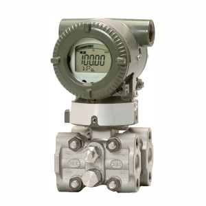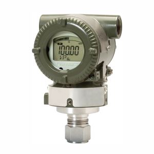
1. General Introduction
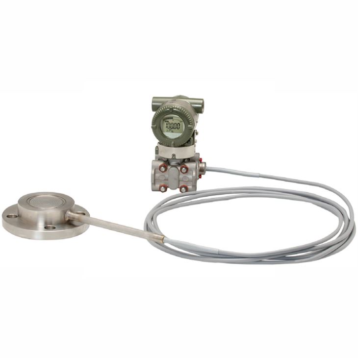
EJA438E Diaphragm Sealed Gauge Pressure Transmitters can be used to measure gauge pressure of liquid, gas, or steam, especially for high temperature process which up to 310°C, standard flange connection with 112/", 2", 3" and 4", flush and extend type flange selectable with pressure rating up to 600lbs; standard capillary up to 10 meters.
2. Measuring Span & Range limits
Measurement Span/Range | MPa | inH2O (/D1) | mbar (/D3) |
mmH2O (/D4) | ||
A | Span | 0.06 to 3.5 | 8.6 to 500 | 0.6 to 35 | 0.6 to 35 | |
Range | -0.1 to 3.5 | -14.5 to 500 | -1 to 35 | -1 to 35 | ||
B |
Flush type | Span | 0.46 to 16 | 67 to 2300 | 4.6 to 160 | 4.6 to 160 |
Range | -0.1 to 16 | -14.5 to 2300 | -1 to 160 | -1 to 160 | ||
Extended type | Span | 0.46 to 7 | 67 to 1000 | 4.6 to 70 | 4.6 to 70 | |
Range | -0.1 to 7 | -14.5 to 1000 | -1 to 70 | -1 to 70 | ||
3. Process temperature, Ambient temperature, and Working pressure
Liquid Fill | Code | Process temperature* | Ambient temperature* | Working pressure |
Silicone oil (general use) | A | –10 to 250°C (14 to 482°F) | –10 to 60°C (14 to 140°F) | 2.7 kPa abs (0.38 psi abs) to flange rating pressure |
Silicone oil (general use) | B | –30 to 180°C (–22 to 356°F) | –15 to 60°C (5 to 140°F) | |
Silicone oil (high temperature use) | C | 10 to 310°C (50 to 590°F) | 10 to 60°C (50 to 140°F) | |
Fluorinated oil (oil-prohibited use) | D | –20 to 120°C (–4 to 248°F) | –10 to 60°C (14 to 140°F) | 51 kPa abs (7.4 psi abs) to flange rating pressure |
Ethylene glycol (low temperature use) | E | –50 to 100°C (–58 to 212°F) | –40 to 60°C (–40 to 140°F) | 100 kPa abs (atmospheric pressure) to flange pressure rating |
Silicone oil (high temp. and high vacuum use) | 1 | –10 to 250°C (14 to 482°F) | –10 to 60°C * (14 to 140°F) | 0.013 kPa abs (0.0019 psi abs) to flange rating pressure |
Silicone oil (high temp. and high vacuum use) | 2 | 10 to 310°C (50 to 590°F) | 10 to 60°C (50 to 140°F) | |
Silicone oil (high vacuum use) | 4 | –10 to 100°C (14 to 212°F) | –10 to 60°C (14 to 140°F) |
4. Flange size and rating
Process connection style | Size | Flange |
Flush type | 3-inch, 2-inch, 11/2-inch | JIS 10K, 20K, 40K, 63K ANSI Class 150, 300, 600 JPI Class 150, 300, 600 DIN PN10/16, 25/40, 64 |
Extended type | 4-inch, 3-inch | JIS 10K, 20K, 40K ANSI Class 150, 300 JPI Class 150, 300 DIN PN10/16, 25/40 |
5. Model and suffix codes
5.1 Transmitter body selection
Main Code | Suffix Codes | Description | |||||||||
EJA438E | Diaphragm gauge pressure transmitter | ||||||||||
Output signal | -D | 4 to 20 mA DC with digital communication (BRAIN protocol) | |||||||||
-J | 4 to 20 mA DC with digital communication (HART 5/HART 7 protocol) | ||||||||||
-F | Digital communication (FOUNDATION Fieldbus protocol) | ||||||||||
-G | Digital communication (PROFIBUS PA protocol) | ||||||||||
-Q | Low Power, 1 to 5 V DC with digital communication (HART 7 protocol) | ||||||||||
Measurement span (capsule) | A | 0.06 to 3.5MPa (8.6 to 500 psi) | |||||||||
B | 0.46 to 16MPa (67 to 2300 psi) | ||||||||||
— | S | Always S | |||||||||
— | C | Always C | |||||||||
Cover flange bolts and nuts material | J | B7 carbon steel | |||||||||
G | 316L SST | ||||||||||
C | 660 SST | ||||||||||
Installation | -9 | Horizontal piping and left side high pressure | |||||||||
Amplifier housing | 1 | Cast aluminum alloy | |||||||||
3 | Cast aluminum alloy with corrosion resistance properties | ||||||||||
2 | ASTM CF-8M stainless steel | ||||||||||
Electrical connection | 0 | G1/2 female, one electrical connection without blind plugs | |||||||||
2 | 1/2 NPT female, two electrical connections without blind plugs | ||||||||||
4 | M20 female, two electrical connections without blind plugs | ||||||||||
5 | G1/2 female, two electrical connections and a blind plug | ||||||||||
7 | 1/2 NPT female, two electrical connections and a blind plug | ||||||||||
9 | M20 female, two electrical connections and a blind plug | ||||||||||
A | G1/2 female, two electrical connections and a SUS316 blind plug | ||||||||||
C | 1/2 NPT female, two electrical connections and a SUS316 blind plug | ||||||||||
D | M20 female, two electrical connections and a SUS316 blind plug | ||||||||||
Integral indicator | D | Digital indicator | |||||||||
E | Digital indicator with the range setting switch (push button) | ||||||||||
N | None | ||||||||||
Mounting bracket | B | 304 SST 2-inch pipe mounting, flat type (for horizontal piping) | |||||||||
J | 316 SST 2-inch pipe mounting, flat type (for horizontal piping) | ||||||||||
N | None | ||||||||||
Optional codes | /Optional codes | ||||||||||
5.2 Diaphragm seal selection 3-inch(80mm)/2-inch(50mm) flush type
Main Code | Suffix Codes | Description | |||||||||||
EJA438E | Transmitter body section (I) | ||||||||||||
Process connection style | -W | Flush type | |||||||||||
Flange rating | J1 | JIS 10K | |||||||||||
J2 | JIS 20K | ||||||||||||
J4 | JIS 40K | ||||||||||||
J6 | JIS 63K | ||||||||||||
A1 | ANSI class 150 | ||||||||||||
A2 | ANSI class 300 | ||||||||||||
A4 | ANSI class 600 | ||||||||||||
D2 | DIN PN10/16 | ||||||||||||
D4 | DIN PN25/40 | ||||||||||||
D5 | DIN PN64 | ||||||||||||
P1 | JPI class 150 | ||||||||||||
P2 | JPI class 300 | ||||||||||||
P4 | JPI class 600 | ||||||||||||
Process connection size (Process flange size) | 3 | 3-inch (80 mm) | |||||||||||
2 | 2-inch (50 mm) | ||||||||||||
Flange material | A | JIS S25C | |||||||||||
B | 304 SST | ||||||||||||
C | 316 SST | ||||||||||||
Gasket contact surface | 1 | Serration (for ANSI flange with wetted parts material SW only) | |||||||||||
2 | Flat (no serration) | ||||||||||||
Wetted parts material | SW | 316L SST Diaphragm, 316L SST Others | |||||||||||
HW | Hastelloy C-276 Diaphragm, Hastelloy C-276 Others | ||||||||||||
TW | Tantalum Diaphragm, Tantalum Others | ||||||||||||
UW | Titanium Diaphragm, Titanium Others | ||||||||||||
Flushing connection ring | 0 | None | |||||||||||
A | Straight type ring, R1/4 connections, 316 SST | ||||||||||||
B | Straight type ring, 1/4NPT connections, 316 SST | ||||||||||||
Extension | 0 | None | |||||||||||
Fill fluid | -A | For general (silicone oil), Process–10 to 250°C, Ambient–10 to 60°C | |||||||||||
-B | For general (silicone oil), Process–30 to 180°C, Ambient–15 to 60°C | ||||||||||||
-C | For high temperature (silicone oil), Process 10 to 310°C, Ambient10 to 60°C | ||||||||||||
-D | For oil-prohibited (fluorinated oil), Process-20 to 120°C, Ambient-10 to 60°C | ||||||||||||
-E | For low temperature (ethylene glycol), Process-50 to 100°C, Ambient-40 to 60°C | ||||||||||||
-1 | For high temp. & vacuum (silicone oil), Process-10 to 250°C, Ambient-10 to 60°C | ||||||||||||
-2 | For high temp. & vacuum (silicone oil), Process10 to 310°C, Ambient10 to 60°C | ||||||||||||
-4 | For high vacuum (silicone oil), Process-10 to 100°C, Ambient-10 to 60°C | ||||||||||||
Capillary connection | A | Side of diaphragm seal unit | |||||||||||
— | 2 | Always 2 | |||||||||||
Capillary length* | 1 | 1m | |||||||||||
2 | 2m | ||||||||||||
3 | 3m | ||||||||||||
4 | 4m | ||||||||||||
5 | 5m | ||||||||||||
6 | 6m | ||||||||||||
7 | 7m | ||||||||||||
8 | 8m | ||||||||||||
9 | 9m | ||||||||||||
A | 10m | ||||||||||||
Optional codes | /Optional codes | ||||||||||||
5.3 Diaphragm seal selection 1-1/2inch(40mm) flush type
Main Code | Suffix Codes | Description | |||||||||||
EJA438E | Transmitter body section (I) | ||||||||||||
Process connection style | -W | Flush type | |||||||||||
Flange rating | J1 | JIS 10K | |||||||||||
J2 | JIS 20K | ||||||||||||
J4 | JIS 40K | ||||||||||||
A1 | ANSI class 150 | ||||||||||||
A2 | ANSI class 300 | ||||||||||||
A4 | ANSI class 600 | ||||||||||||
P1 | JPI class 150 | ||||||||||||
P2 | JPI class 300 | ||||||||||||
P4 | JPI class 600 | ||||||||||||
Process connection size (Process flange size) | 8 | 1-1/2-inch (40 mm) | |||||||||||
Flange material | A | JIS S25C | |||||||||||
B | 304 SST | ||||||||||||
C | 316 SST | ||||||||||||
Gasket contact surface | 1 | Serration (for ANSI flange with wetted parts material SW only) | |||||||||||
2 | Flat (no serration) | ||||||||||||
Wetted parts material | SW | 316L SST Diaphragm, 316L SST Others | |||||||||||
Flushing connection ring | C | Reducer type ring, R1/4 connections, 316 SST | |||||||||||
D | Reducer type ring, 1/4NPT connections, 316 SST | ||||||||||||
Extension | 0 | None | |||||||||||
Fill fluid | -A | For general (silicone oil), Process–10 to 250°C, Ambient–10 to 60°C | |||||||||||
-B | For general (silicone oil), Process–30 to 180°C, Ambient–15 to 60°C | ||||||||||||
-D | For oil-prohibited (fluorinated oil), Process-20 to 120°C, Ambient-10 to 60°C | ||||||||||||
-E | For low temperature (ethylene glycol), Process-50 to 100°C, Ambient-40 to 60°C | ||||||||||||
-1 | For high temp. & vacuum (silicone oil), Process-10 to 250°C, Ambient-10 to 60°C | ||||||||||||
-4 | For high vacuum (silicone oil), Process-10 to 100°C, Ambient-10 to 60°C | ||||||||||||
Capillary connection | A | Side of diaphragm seal unit | |||||||||||
— | 2 | Always 2 | |||||||||||
Capillary length* | 1 | 1m | |||||||||||
2 | 2m | ||||||||||||
3 | 3m | ||||||||||||
4 | 4m | ||||||||||||
5 | 5m | ||||||||||||
6 | 6m | ||||||||||||
7 | 7m | ||||||||||||
8 | 8m | ||||||||||||
9 | 9m | ||||||||||||
A | 10m | ||||||||||||
Optional codes | /Optional codes | ||||||||||||
5.4 Diaphragm seal selection 4-inch(100mm)/3-inch(80mm) extend type
Main Code | Suffix Codes | Description | |||||||||||
EJA438E | Transmitter body section (I) | ||||||||||||
Process connection style | -E | Extended type | |||||||||||
Flange rating | J1 | JIS 10K | |||||||||||
J2 | JIS 20K | ||||||||||||
J4 | JIS 40K | ||||||||||||
A1 | ANSI class 150 | ||||||||||||
A2 | ANSI class 300 | ||||||||||||
P1 | JPI class 150 | ||||||||||||
P2 | JPI class 300 | ||||||||||||
D2 | DIN PN10/16 | ||||||||||||
D4 | DIN PN25/40 | ||||||||||||
Process connection size (Process flange size) | 4 | 4-inch (100 mm) | |||||||||||
3 | 3-inch (80 mm) | ||||||||||||
Flange material | A | JIS S25C | |||||||||||
B | 304 SST | ||||||||||||
C | 316 SST | ||||||||||||
Gasket contact surface | 1 | Serration (for ANSI flange with wetted parts material SW only) | |||||||||||
2 | Flat (no serration) | ||||||||||||
Wetted parts material | SE | 316L SST Diaphragm, 316L SST Others | |||||||||||
Flushing connection ring | 0 | None | |||||||||||
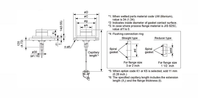
Extension | 1 | Length (X2) = 50 mm | |||||||||||
3 | Length (X2) = 100 mm | ||||||||||||
5 | Length (X2) = 150 mm | ||||||||||||
Fill fluid | -A | For general (silicone oil), Process–10 to 250°C, Ambient–10 to 60°C | |||||||||||
-B | For general (silicone oil), Process–30 to 180°C, Ambient–15 to 60°C | ||||||||||||
-C | For high temperature (silicone oil), Process100 to 310°C, Ambient10 to 60°C | ||||||||||||
-D | For oil-prohibited (fluorinated oil), Process-20 to 120°C, Ambient-10 to 60°C | ||||||||||||
-E | For low temperature (ethylene glycol), Process-50 to 100°C, Ambient-40 to 60°C | ||||||||||||
-1 | For high temp. & vacuum (silicone oil), Process-10 to 250°C, Ambient-10 to 60°C | ||||||||||||
-2 | For high temp. & vacuum (silicone oil), Process10 to 310°C, Ambient10 to 60°C | ||||||||||||
-4 | For high vacuum (silicone oil), Process-10 to 100°C, Ambient-10 to 60°C | ||||||||||||
Capillary connection | B | Back of diaphragm seal unit | |||||||||||
— | 2 | Always 2 | |||||||||||
Capillary length* | 1 | 1m | |||||||||||
2 | 2m | ||||||||||||
3 | 3m | ||||||||||||
4 | 4m | ||||||||||||
5 | 5m | ||||||||||||
6 | 6m | ||||||||||||
7 | 7m | ||||||||||||
8 | 8m | ||||||||||||
9 | 9m | ||||||||||||
A | 10m | ||||||||||||
Optional codes | /Optional codes | ||||||||||||
6. Mounting & Dimensions
● Flush type

● Extended type