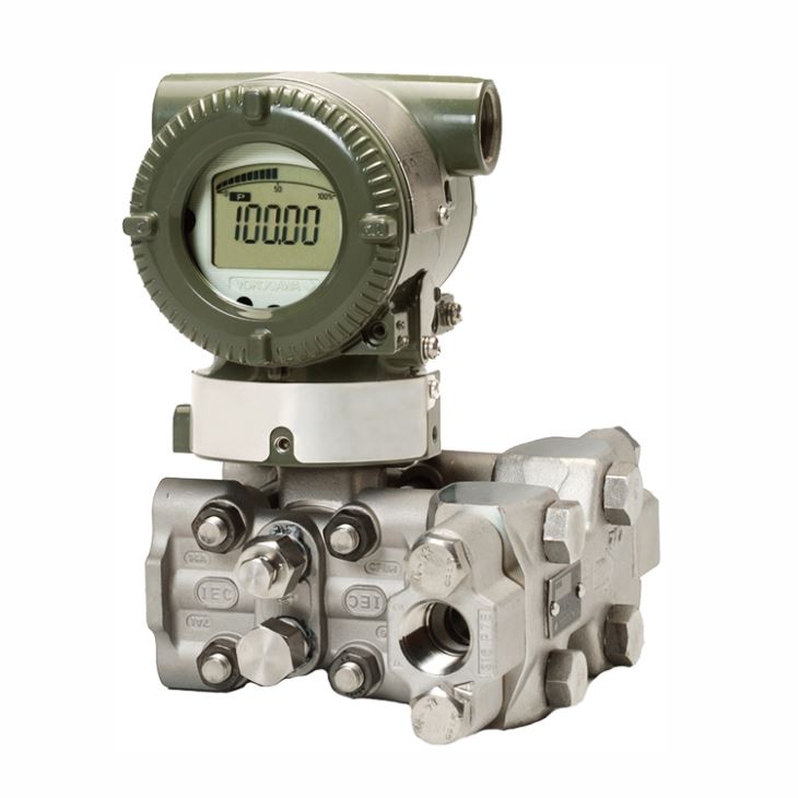
1. General Introduction
EJA115E low flow transmitter is a differential pressure transmitter assembled with an integral orifice and excellent for very low flow measurement, applicable for liquid flow range up to 33liter /minute and gas flow range up to 910Nl/min. FM, ATEX, Canadian Standards Association (CSA), IECEx and NEPSI Explosion proof Approval are selectable for different of design standard and local regulations.
For CSA Explosionproof Approval with suffix code CF1: Certificate: 2014354, Applicable Standard: C22.2 No.0, C22.2 No.0.4, C22.2 No.0.5, C22.2 No.25, C22.2 No.30, C22.2 No.94, C22.2 No.60079-0, C22.2 No.60079-1, C22.2 No.61010-1; Explosion-proof for Class I, Groups B, C and D. Dust ignition-proof for Class II/III, Groups E, F and G.When installed in Division 2, "SEAL NOT REQUIRED" Enclosure: NEMA TYPE 4X, Temp. Code: T6...T4, Ex d IIC T6...T4, Enclosure: IP66/IP67; Max. Process Temp.: T4;120℃(248℉), T5;100℃(212℉), T6; 85℃(185℉); Ambient .Temp.: –50 to 75℃(–58 to 167℉) for T4, –50 to 80℃(–58 to 176℉) for T5, –50 to 75℃(–58 to 167℉) for T6. Process Sealing Certification: Dual Seal Certified by CSA to the requirement of ANSI/ISA 12.27.01, No additional sealing required, Primary seal failure annunciation: at the zero adjustment screw.
For CSA Intrinsically safe Approval with suffix code CS1: Certificate: 1606623 [For CSA C22.2], Applicable Standard: C22.2 No.0, C22.2 No.0.4, C22.2 No.25, C22.2 No.94, C22.2 No.157, C22.2 No.213, C22.2 No.61010-1, C22.2 No.60079-0, Intrinsically Safe for Class I, Division 1, Groups A, B, C & D, Class II, Division 1, Groups E, F & G, Class III, Division 1, Non-incendive for Class I, Division 2, Groups A, B, C & D, Class II, Division 2, Groups F & G, Class III, Division 1; Enclosure: NEMA TYPE 4X, Temp. Code: T4 Amb. Temp.: –50 to 60℃(–58 to 140℉) , Electrical Parameters: [Intrinsically Safe] Vmax=30V, Imax=200mA, Pmax=0.9W, Ci=10nF, Li=0 μH, [Non-incendive] Vmax=30V, Ci=10nF, Li=0 μH; [For CSA E60079], Applicable Standard: CAN/CSA E60079-11, CAN/CSA E60079-15, IEC 60529:2001, Ex ia IIC T4, Ex nL IIC T4 Enclosure: IP66/IP67; Ambient Temp.: –50 to 60℃(–58 to 140℉) *2, Max. Process Temp.: 120℃(248℉); Electrical Parameters: [Ex ia] Ui=30V, Ii=200mA, Pi=0.9W, Ci=10nF, Li=0 μH, [Ex nL] Ui=30V, Ci=10nF, Li=0 μH; Process Sealing Certification: Dual Seal Certified by CSA to the requirement of ANSI/ISA 12.27.01, No additional sealing required, Primary seal failure annunciation: at the zero adjustment screw.
For IECEx Flameproof Approval with suffix code SF2: Applicable Standard: IEC 60079-0:2011, IEC60079-1:2007-4, Certificate: IECEx CSA 07.0008, Flameproof for Zone 1, Ex d IIC T6...T4 Gb Enclosure: IP66/IP67, Max.Process Temp.: T4;120℃(248℉), T5;100℃(212℉), T6; 85℃(185℉), Ambient Temp.: –50 to 75℃(–58 to 167℉) for T4, –50 to 80℃(–58 to 176℉) for T5, –50 to 75℃(–58 to 167℉) for T6.
2. Measuring Span & Range limits
Capsule | Differential Pressure | Water Equivalent Flow (l/min) | Air Equivalent Flow (Nl/min) |
F | 1 to 5 kPa (100 to 500 mmH2O) | 0.016 to 5.0 | 0.44 to 140 |
M | 2 to 100 kPa (200 to 10000 mmH2O) | 0.022 to 23.0 | 0.63 to 635 |
H | 20 to 210 kPa (2000 to 21000 mmH2O) | 0.07 to 33.0 | 2.0 to 910 |
3. Model and suffix codes
Main Code | Suffix Codes | Description | |||||||||
EJA115E | Low flow transmitter | ||||||||||
Output signal | -D | 4 to 20 mA DC with digital communication (BRAIN protocol) | |||||||||
-J | 4 to 20 mA DC with digital communication (HART 5/HART 7 protocol) | ||||||||||
-F | Digital communication (FOUNDATION Fieldbus protocol) | ||||||||||
-G | Digital communication (PROFIBUS PA protocol) | ||||||||||
-Q | Low Power, 1 to 5 V DC with digital communication (HART 7 protocol) | ||||||||||
Measurement span (capsule) | F | 1 to 5 kPa (4 to 20 inH2O) | |||||||||
M | 2 to 100 kPa (8 to 400 inH2O) | ||||||||||
H | 20 to 210 kPa (80 to 840 inH2O) | ||||||||||
Wetted parts material | S | Cover flange and process connector: ASTM CF-8M Capsule: Hastelloy C-276 (Diaphragm), F316L SST, 316L SST (Others) Capsule gasket: Teflon-coated 316L SST Vent/Drain plug: 316 SST # Orifice: 316 SST Manifold: F316 SST Spacer: 316 SST Orifice gasket: PTFE | |||||||||
Process connections | 2 | with Rc1/2 female process connector | |||||||||
4 | with 1/2 NPT female process connector | ||||||||||
Bolts and nuts material | J | B7 carbon steel | |||||||||
G | 316L SST | ||||||||||
Installation | -2 | Vertical piping, right side high pressure, manifold upside | |||||||||
-3 | Vertical piping, right side high pressure, manifold downside | ||||||||||
-6 | Vertical piping, left side high pressure, manifold upside | ||||||||||
-7 | Vertical piping, left side high pressure, and manifold downside | ||||||||||
-8 | Horizontal piping and right side high pressure | ||||||||||
-9 | Horizontal piping and left side high pressure | ||||||||||
Amplifier housing | 1 | Cast aluminum alloy | |||||||||
3 | Cast aluminum alloy with corrosion resistance properties | ||||||||||
2 | ASTM CF-8M stainless steel | ||||||||||
Electrical connection | 0 | G1/2 female, one electrical connection without blind plugs | |||||||||
2 | 1/2 NPT female, two electrical connections without blind plugs | ||||||||||
4 | M20 female, two electrical connections without blind plugs | ||||||||||
5 | G1/2 female, two electrical connections and a blind plug | ||||||||||
7 | 1/2 NPT female, two electrical connections and a blind plug | ||||||||||
9 | M20 female, two electrical connections and a blind plug | ||||||||||
A | G1/2 female, two electrical connections and a SUS316 blind plug | ||||||||||
C | 1/2 NPT female, two electrical connections and a SUS316 blind plug | ||||||||||
D | M20 female, two electrical connections and a SUS316 blind plug | ||||||||||
Integral indicator | D | Digital indicator | |||||||||
E | Digital indicator with the range setting switch (push button) | ||||||||||
N | None | ||||||||||
Mounting bracket | B | 304 SST 2-inch pipe mounting, flat type (for horizontal piping) | |||||||||
D | 304 SST 2-inch pipe mounting, L type (for vertical piping) | ||||||||||
J | 316 SST 2-inch pipe mounting, flat type (for horizontal piping) | ||||||||||
K | 316 SST 2-inch pipe mounting, L type (for vertical piping) | ||||||||||
N | None | ||||||||||
Optional codes | /Optional codes | ||||||||||
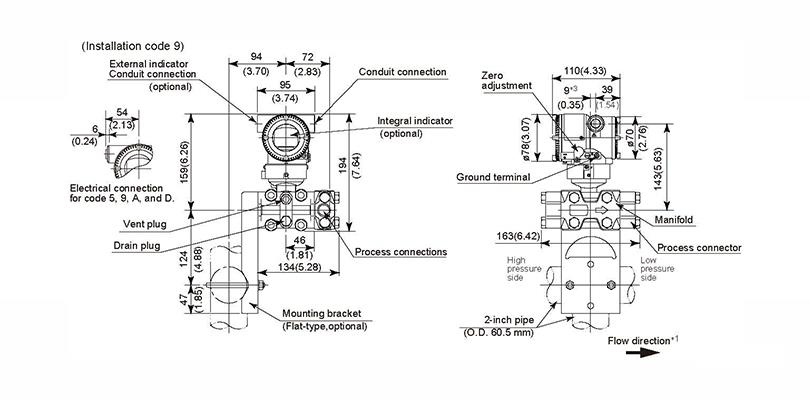
4. Mounting & Dimensions
◆ Vertical Impulse Piping Type Installation Code ‘6’ and ‘7’
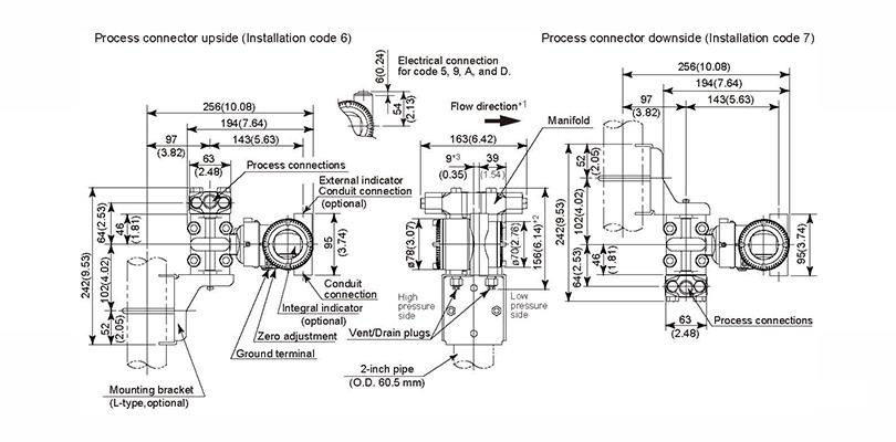
◆ Horizontal Impulse Piping Type Installation Code ‘9’