1. General Introduction
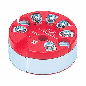
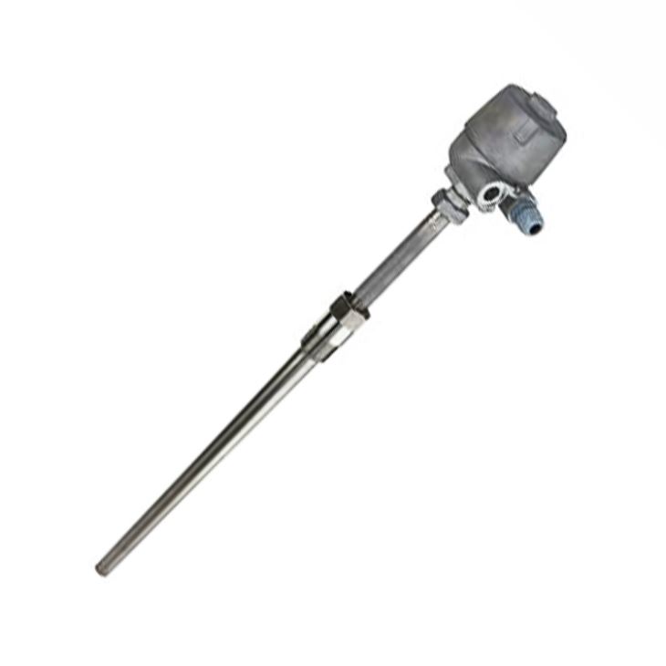
ABB TSP331 temperature transmitter is a heavy duty modular type sensor with a drilled bar stock thermowell which is mounted to flange by screw-in thread, terminal box is compression fitting type, sensor can be replaced during operation, transmitter head can be either integrated or remote mounted, both RTD and thermocouple sensors accepted, sensor meets SIL2 approval when integrated with transmitter. Both TTH200 and TTH300 can be integrated; recommend using an LC display with type AS display function if using a TTH200 and LCD indicator with type A if using TTH300.
2. Compare table of TSP311 TPS321 and TSP311
Type | TSP311 | TSP321 | TSP331 |
Design | No thermowell, for installation in existing thermowell | Welded protective fitting manufactured from pipe material | Drilled thermowell manufactured from bar stock material |
Measuring inset, extension tube with thermowell interface, connection head, transmitter, optional LCD display | |||
Process connection | Insertion in an existing thermowell.
| Screw-in thread, flange, compression fitting | Welded connections, screw-in thread, flange |
Transport temperature / Storage temperature | -20 to 70℃ (-4 to 158 °F) | ||
Maximum temperature limits | (depending on the sensor and material selected, the lower temperature value in each case counts) | ||
Sensor | Thin film resistor: 400℃(752 °F), wire wound resistor: 800℃ (1472 °F), Thermocouples type K, N, J, E, L, S: 1600℃ (2912 °F) | ||
Material | Temperature limits | ||
316L / 1.4404 | ≤ 800℃ (1472 °F) | ||
316Ti / 1.4571 | ≤ 800℃ (1472 °F) | ||
Inconel 600 / 2.4816 | ≤ 1100℃ (2012 °F) | ||
Hastelloy C276 / 2.4819 | — | ≤ 1100℃ (2012 °F) | ≤ 1100℃ (2012 °F) |
Monel 400 / 2.4360 | — | — | 600℃ (1112 °F) |
1.7335 | — | — | ≤ 540℃ (1004 °F) |
1.7380 | — | — | ≤ 570℃ (1058 °F) |
1.5415 | — | — | ≤ 500℃ (932 °F) |
E-CTFE | — | ≤ 120℃ (248 °F) | ≤ 120℃ (248 °F) |
Tantalum | — | ≤ 250℃ (482 °F) | ≤ 250℃ (482 °F) |
Pressure | Maximum 40 ... 100 bar (580.15 bar ... 1450.38 psi) | Maximum 700 bar (10152.64 psi) | |
3. Basic code selection of TSP331 temperature transmitter
Main Code | Suffix Codes | Description | |||||||||||||
TSP331 | SensyTemp TSP331 Temperature Sensor, with drilled thermowell, for heavy duty applications | ||||||||||||||
Explosion Protection / Approvals | Y0 | Without explosion protection | |||||||||||||
A1 | Intrinsic Safety ATEX II 1 G Ex ia IIC T6 Ga or II 2 G Ex ib IIC T6 Gb or II 1/2 G Ex ib IIC T6 Ga/Gb | ||||||||||||||
A3 | Dust ignition proof ATEX II 1 D IP6x | ||||||||||||||
A4 | Dust ignition proof ATEX II 1 D IP6x T133 ... T400 and Intrinsic Safety ATEX II 1 G Ex ia IIC T6 | ||||||||||||||
A5 | Flameproof enclosure ATEX II 1/2 G Ex d IIC T1 - T6 Ga/Gb | ||||||||||||||
B1 | Non incentive ATEX II 3 G Ex nA IIC T1 - T6 Gc and ATEX II 3 D Ex tc IIIB T133°C Dc | ||||||||||||||
B5 | Dust ignition proof ATEX II 1 D IP6x T133 and Flameproof enclosure ATEX II 1/2 G Ex d IIC T6 | ||||||||||||||
H1 | Intrinsic Safety IECEx ia IIC T6 Ga | ||||||||||||||
H2 | Intrinsic Safety IECEx ib IIC T6 Gb or IECEx ib IIC T6 Ga/Gb | ||||||||||||||
H5 | Flameproof enclosure IECEx d IIC T1 - T6 Ga/Gb | ||||||||||||||
N1 | Intrinsic Safety acc. NAMUR NE 24 and ATEX II 1 G Ex ia IIC T6 Ga | ||||||||||||||
G1 | GOST Russia - metrological approval | ||||||||||||||
P2 | GOST Russia - metrological approval and EAC-Ex, Ex i - Zone 0 | ||||||||||||||
P3 | GOST Russia - metrological approval and EAC-Ex, Ex d | ||||||||||||||
P4 | GOST Russia - metrological approval and EAC-Ex, dust ignition proof | ||||||||||||||
G3 | GOST Kazakhstan - metrological approval | ||||||||||||||
T2 | GOST Kazakhstan - metrological approval and EAC-Ex, Ex i - Zone 0 | ||||||||||||||
T3 | GOST Kazakhstan - metrological approval and EAC-Ex, Ex d | ||||||||||||||
T4 | GOST Kazakhstan - metrological approval and EAC-Ex, dust ignition proof | ||||||||||||||
M5 | GOST Belarus - metrological approval | ||||||||||||||
U2 | GOST Belarus - metrological approval and EAC-Ex, Ex i - Zone 0 | ||||||||||||||
U3 | GOST Belarus - metrological approval and EAC-Ex, Ex d | ||||||||||||||
U4 | GOST Belarus - metrological approval and EAC-Ex, dust ignition proof | ||||||||||||||
Wetted Thermo well Material | S1 | Stainless Steel ASTM 316L (1.4404) | |||||||||||||
S2 | Stainless Steel ASTM 316Ti (1.4571) | ||||||||||||||
W1 | Heat-resistant stainless steel ASTM A182 F12 (1.7335) | ||||||||||||||
W2 | Heat-resistant stainless steel ASTM A182 F22 (1.7380) | ||||||||||||||
W3 | Heat-resistant stainless steel ASTM A182 F1 (1.5415) | ||||||||||||||
W4 | Highly heat-resistant stainless steel ASTM A347 H (1.4961) | ||||||||||||||
H1 | Highly heat-resistant stainless steel ASTM A446-1 (1.4749) | ||||||||||||||
H2 | Heat resistant steel ASTM A446 (1.4762) | ||||||||||||||
H3 | Heat resistant steel ASTM A314 (CrNi, 1.4841) | ||||||||||||||
S9 | Duplex stainless steel (CrNi, 1.4462) | ||||||||||||||
S4 | Stainless steel ASTM 904L (CrNi, 1.4539); (Uranus B6) | ||||||||||||||
N1 | Ni-Alloy Hastelloy C-276 (2.4819) | ||||||||||||||
N2 | Ni-Alloy Hastelloy C-4 (2.4610) | ||||||||||||||
N4 | NiCu-Alloy Monel 400 (2.4360) | ||||||||||||||
H4 | Ni-Alloy Incoloy 800 (1.4876) | ||||||||||||||
N5 | Highly heat-resistant stainless steel , Ni-Alloy Inconel 600 (2.4816) | ||||||||||||||
W5 | Highly heat-resistant stainless steel ASTM A182 F91 (1.4903) | ||||||||||||||
S5 | Stainless steel ASTM 304 (CrNi, 1.4301) | ||||||||||||||
S6 | Stainless steel ASTM 321 (CrNi, 1.4541) | ||||||||||||||
C1 | Carbon steel ASTM A105 (1.0460) | ||||||||||||||
Z9 | Others | ||||||||||||||
Thermowell Type | D1 | Weld-in thermowell from bar stock material, diameter F2 = 24 mm (0.95 in.), (DIN 43772, Form 4) | |||||||||||||
D2 | Weld-in thermowell from bar stock material, diameter F2 = 18 mm (0.71 in.), (DIN 43772, Form 4) | ||||||||||||||
D3 | Flanged thermowell from bar stock material, diameter F2 = 24 mm (0.95 in.), (DIN 43772, Form 4F) | ||||||||||||||
D4 | Flanged thermowell from bar stock material, diameter F2 = 18 mm (0.71 in.), (ABB-Form 4FS) | ||||||||||||||
D5 | Weld-in thermowell from bar stock material, diameter F2 = 26 mm (1.02 in.), (DIN 43772, Form 4) | ||||||||||||||
D6 | Flanged thermowell from bar stock material, diameter F2 = 26 mm (1.02 in.), (DIN 43772, Form 4F) | ||||||||||||||
R1 | Weld-in thermowell from bar stock material, (ABB, Form DR ) | ||||||||||||||
R2 | Flanged thermowell from bar stock material, (ABB, Form DRF ) | ||||||||||||||
R3 | Weld-in thermowell from bar stock material, ( ABB, Form RD ) | ||||||||||||||
R4 | Flanged thermowell from bar stock material, ( ABB, Form RDF ) | ||||||||||||||
P1 | Weld-in thermowell from bar stock material, (ABB, Form PW) | ||||||||||||||
P2 | Flanged thermowell from bar stock material, (ABB, Form PF) | ||||||||||||||
P3 | Screwed thermowell from bar stock material, tapered tip, (ABB, Form PS) | ||||||||||||||
S1 | Screwed tubular thermowell from bar stock material, straight shaft (DIN 43772, Form 6) | ||||||||||||||
Z9 | Others | ||||||||||||||
Process Connection | Y00 | Without process connection | |||||||||||||
F03 | Flange DN 25 PN 10 ... PN 40, EN 1092-1 | ||||||||||||||
F29 | Flange DN 25 PN 63 ... PN100, EN 1092-1 | ||||||||||||||
F30 | Flange DN 32 PN 16 … PN 40, EN 1092-1 | ||||||||||||||
F04 | Flange DN 40 PN 10 ... PN 40, EN 1092-1 | ||||||||||||||
F37 | Flange DN 40 PN 63 ... PN 100, EN 1092-1 | ||||||||||||||
F06 | Flange DN 50 PN 6, EN 1092-1 | ||||||||||||||
F05 | Flange DN 50 PN 10 ... PN 40, EN 1092-1 | ||||||||||||||
F33 | Flange DN 50 PN 63, EN 1092-1 | ||||||||||||||
F34 | Flange DN 50 PN 100, EN 1092-1 | ||||||||||||||
F35 | Flange DN 80 PN 16, EN 1092-1 | ||||||||||||||
F36 | Flange DN 100 PN 40, EN 1092-1 | ||||||||||||||
F07 | Flange 1 in. 150 lbs, ASME B16.5 | ||||||||||||||
F08 | Flange 1 in. 300 lbs, ASME B16.5 | ||||||||||||||
F09 | Flange 1 in. 600 lbs, ASME B16.5 | ||||||||||||||
F11 | Flange 1-1/2 in. 150 lbs, ASME B16.5 | ||||||||||||||
F12 | Flange 1-1/2 in. 300 lbs, ASME B16.5 | ||||||||||||||
F13 | Flange 1-1/2 in. 600 lbs, ASME B16.5 | ||||||||||||||
F14 | Flange 1-1/2 in. 900 / 1500 lbs, ASME B16.5 | ||||||||||||||
F15 | Flange 2 in. 150 lbs, ASME B16.5 | ||||||||||||||
F16 | Flange 2 in. 300 lbs, ASME B16.5 | ||||||||||||||
F17 | Flange 2 in. 600 lbs, ASME B16.5 | ||||||||||||||
F18 | Flange 2 in. 900/1500 lbs, ASME B16.5 | ||||||||||||||
S04 | Conical thread 1/2 in. NPT | ||||||||||||||
S05 | Conical thread 3/4 in. NPT | ||||||||||||||
S06 | Conical thread 1 in. NPT | ||||||||||||||
Z99 | Others | ||||||||||||||
Extension Tube Length | K1 | K = 150 mm (6 in.) | |||||||||||||
Z9 | Customer specific length | ||||||||||||||
Thermowell Connection | G1 | Extension tube with Cylindrical thread G 1/2 A | |||||||||||||
G2 | Extension tube with Cylindrical thread G 3/4 A | ||||||||||||||
G3 | Extension tube with Cylindrical thread G 3/8 A | ||||||||||||||
M1 | Extension tube with Cylindrical thread M14 x 1,5 | ||||||||||||||
M2 | Extension tube with Cylindrical thread M18 x 1,5 | ||||||||||||||
M3 | Extension tube with Cylindrical thread M20 x 1,5 | ||||||||||||||
M4 | Extension tube with Cylindrical thread M24 x 1,5 | ||||||||||||||
N1 | Extension tube with conycal thread 1/2 in. NPT | ||||||||||||||
N2 | Nipple / 1/2 in. NPT / 1/2 in. NPT | ||||||||||||||
N3 | Nipple-Union / 1/2 in. NPT / Union 1/2 in. NPT | ||||||||||||||
N4 | Nipple - Union - Nipple / 1/2 in. NPT / 1/2 in. NPT | ||||||||||||||
U6 | Extension with Male nut, thread G 1/2 in. | ||||||||||||||
Z9 | Others | ||||||||||||||
Immersion Length | Y0 | Without fixed immersion length | |||||||||||||
D1 | U = 130 mm (5.2 in.) | ||||||||||||||
D2 | U = 190 mm (7.5 in.) | ||||||||||||||
D3 | U = 340 mm (13.4 in.) | ||||||||||||||
P1 | U = 100 mm (4 in.) | ||||||||||||||
P2 | U = 150 mm (6 in.) | ||||||||||||||
P3 | U = 200 mm (8 in.) | ||||||||||||||
P4 | U = 250 mm (10 in.) | ||||||||||||||
P5 | U = 300 mm (12 in.) | ||||||||||||||
P6 | U = 350 mm (14 in.) | ||||||||||||||
Z9 | Customer specific length | ||||||||||||||
Thermowell Length | D1 | L = 110 mm (4.4 in.), C = 65 mm (2.5 in.) | |||||||||||||
D2 | L = 115 mm (4.6 in.), C = 40 mm (1.5 in.) | ||||||||||||||
D3 | L = 140 mm (5.6 in.), C = 65 mm (2.5 in.) | ||||||||||||||
D4 | L = 200 mm (8 in.), C = 65 mm (2.5 in.) | ||||||||||||||
D5 | L = 200 mm (8 in.), C = 125 mm (5 in.) | ||||||||||||||
D6 | L = 260 mm (10.3 in.), C = 125 mm (5 in.) | ||||||||||||||
D7 | L = 410 mm (16.2 in.), C = 275 mm (10.9 in.) | ||||||||||||||
R1 | L = 146 mm (5.8 in.) | ||||||||||||||
R2 | L = 175 mm (6.9 in.) | ||||||||||||||
R3 | L = 265 mm (10.5 in.) | ||||||||||||||
R4 | L = 415 mm (16.4 in.) | ||||||||||||||
P1 | L = U + 65 mm (2.5 in.) - ABB-standard | ||||||||||||||
D9 | Acc. customer specification | ||||||||||||||
Z9 | Customer specific length | ||||||||||||||
Measuring Inset Type | Y0 | Without measuring inset | |||||||||||||
S1 | RTD, TF, Basic application, measuring range -50 ... 400 °C (-58 ... 752 °F), 10 g | ||||||||||||||
S2 | RTD, TF, Extended vibration resistance, measuring range -50 ... 400 °C (-58 ... 752°F), 60 g | ||||||||||||||
S3 | RTD, TF, Extended measuring range -196 ... 400°C (-321 ... 752°F), 10 g | ||||||||||||||
S4 | RTD, TF, Extended vibration resistance, extendend measuring range -196 ... 400°C (-321 ... 752°F), 60 g | ||||||||||||||
D1 | RTD, WW, Extended measuring range -196 ... 600°C (-321 ... 1112°F), 10 g | ||||||||||||||
D3 | RTD, WW, Extended vibration resistance, extendend measuring range -196 ... 600°C (-321 ... 1112°F), 60 g | ||||||||||||||
E1 | RTD, adjustable to German calibration regulations, sign of app. 000/308 - without calibration | ||||||||||||||
E2 | RTD, custody preliminary, adjustable to German calibration regulations, sign of app. 000/308 - with calibration -10°C and +50°C | ||||||||||||||
T1 | Thermocouple | ||||||||||||||
Z9 | Others | ||||||||||||||
Sensor Type and Wiring | Y0 | Without measuring inset | |||||||||||||
P1 | 1 x Pt100, 2-wire | ||||||||||||||
P2 | 1 x Pt100, 3-wire | ||||||||||||||
P3 | 1 x Pt100, 4-wire | ||||||||||||||
P4 | 2 x Pt100, 2-wire | ||||||||||||||
P5 | 2 x Pt100, 3-wire | ||||||||||||||
P6 | 2 x Pt100, 4-wire | ||||||||||||||
P8 | 1 x Pt1000, 2-wire | ||||||||||||||
P7 | 1 x Pt1000, 3-wire | ||||||||||||||
P9 | 1 x Pt1000, 4-wire | ||||||||||||||
K1 | 1 x Type K (NiCr-NiAl) | ||||||||||||||
K2 | 2 x Type K (NiCr-NiAl) | ||||||||||||||
K3 | 3 x Type K (NiCr-NiAl) | ||||||||||||||
J1 | 1 x Type J (Fe-CuNi) | ||||||||||||||
J2 | 2 x Type J (Fe-CuNi) | ||||||||||||||
L1 | 1 x Type L (Fe-CuNi) | ||||||||||||||
L2 | 2 x Type L (Fe-CuNi) | ||||||||||||||
N1 | 1 x Type N (NiCrSi-NiSi) | ||||||||||||||
N2 | 2 x Type N (NiCrSi-NiSi) | ||||||||||||||
T1 | 1 x Type T (Cu-CuNi) | ||||||||||||||
T2 | 2 x Type T (Cu-CuNi) | ||||||||||||||
E1 | 1 x Type E (NiCr-CuNi) | ||||||||||||||
E2 | 2 x Type E (NiCr-CuNi) | ||||||||||||||
S1 | 1 x Type S (Pt10Rh-Pt) | ||||||||||||||
S2 | 2 x Type S (Pt10Rh-Pt) | ||||||||||||||
Z9 | Others | ||||||||||||||
Connection Head Type / Material | L1 | AGL / Aluminium, screwed cover | |||||||||||||
L2 | AGLH / Aluminium, high cover, screwed | ||||||||||||||
L4 | AGLD / Aluminium, screwed cover with display | ||||||||||||||
S1 | AGS / Stainless steel, screwed cover | ||||||||||||||
S2 | AGSH / Stainless steel, high cover, screwed | ||||||||||||||
S4 | AGSD / Stainless steel, screwed cover with display | ||||||||||||||
Z9 | Others | ||||||||||||||
Sensor Accuracy | Y0 | Without measuring inset | |||||||||||||
B2 | Accuracy Class B, IEC 60751 | ||||||||||||||
D2 | Wire Wound, Double, Accuracy Class A, IEC 60751, Range 0 ... 250 °C (32 ... 482 °F) | ||||||||||||||
D1 | Wire Wound, Accuracy Class A, IEC 60751, Range -100 ... 450°C (-148 ... 842 °F) | ||||||||||||||
S1 | Thin Film, Accuracy Class A, IEC 60751, Range -30 ... 300°C (-22 ... 572 °F) | ||||||||||||||
S3 | Thin Film, Accuracy Class AA, IEC 60751, Range 0 ... 100 °C (0 ... 212 °F) | ||||||||||||||
S6 | Thin Film, Accuracy Class A extended according to IEC 60751, Range -196 ... 400°C (-320,8 ... 752 °F | ||||||||||||||
S8 | Thin Film, Accuracy Class AA extended according to IEC 60751, Range -196 ... 400°C (-320,8 ... 752 °F) | ||||||||||||||
T2 | Thermocouple, Accuracy Class 2, IEC 60584 | ||||||||||||||
T1 | Thermocouple, Accuracy Class 1, IEC 60584 | ||||||||||||||
T4 | Thermocouple, Standard Accuracy ANSI MC96.1 | ||||||||||||||
T3 | Thermocouple, Special Accuracy ANSI MC96.1 | ||||||||||||||
T5 | Thermocouple, Accuracy according to DIN 43710 | ||||||||||||||
Z9 | Others | ||||||||||||||
Connection Head Type / Material | L1 | AGL / Aluminium, screwed cover | |||||||||||||
L2 | AGLH / Aluminium, high cover, screwed | ||||||||||||||
L4 | AGLD / Aluminium, screwed cover with display | ||||||||||||||
S1 | AGS / Stainless steel, screwed cover | ||||||||||||||
S2 | AGSH / Stainless steel, high cover, screwed | ||||||||||||||
S4 | AGSD / Stainless steel, screwed cover with display | ||||||||||||||
Z9 | Others | ||||||||||||||
Transmitter | Y1 | Without transmitter, sensor with ceramic terminal block - spring loaded | |||||||||||||
Y2 | Without transmitter, sensor with flying leads and metal plate - spring loaded | ||||||||||||||
H4 | TTH300-HART, programmable, output signal 4 ... 20 mA, dual input | ||||||||||||||
H5 | TTH300-HART, Ex version, programmable, output signal 4 ... 20 mA, dual input | ||||||||||||||
P6 | TTH300-PA, programmable, output PROFIBUS PA, dual input | ||||||||||||||
P7 | TTH300-PA, Ex version, programmable, output PROFIBUS PA, dual input | ||||||||||||||
F6 | TTH300-FF, programmable, output FOUNDATION fieldbus H1, dual input | ||||||||||||||
F7 | TTH300-FF, Ex version, programmable, output FOUNDATION fieldbus H1, dual input | ||||||||||||||
H6 | TTH200-HART, programmable, output signal 4 ... 20 mA | ||||||||||||||
H7 | TTH200-HART, Ex version, programmable, output signal 4 ... 20 mA | ||||||||||||||
Optional Codes | /Optional codes | ||||||||||||||
4. Installation for Normal Diameter and Small Diameters