1. General Introduction
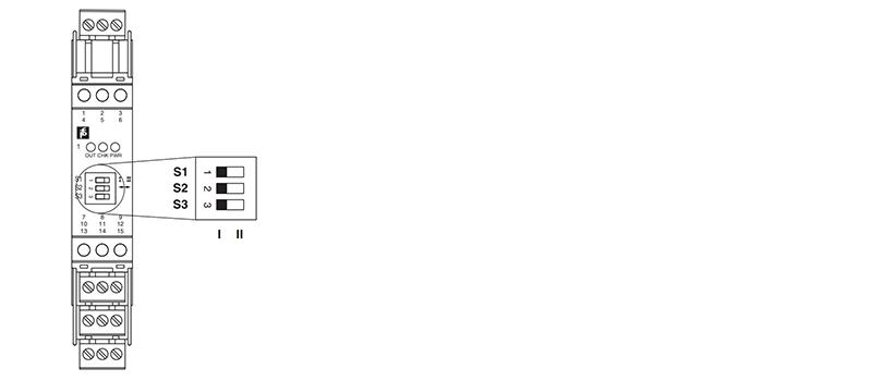
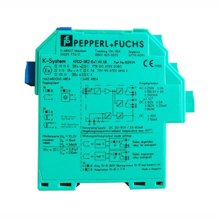
The proximity sensor or switch controls a form C changeover relay contact for the safe area load. The normal output state can be reversed using switch S1. Switch S2 allows output II to be switched between a signal output or an error message output. Switch S3 is used to enable or disable line fault detection of the field circuit. During an error condition, the relays revert to their deenergized state and the LEDs indicate the fault according to NAMUR NE44. A unique collective error messaging feature is available when used with the Power Rail system.
2. General Specification for KFD2-SR2-Ex1.W.LB
Model | KFD2-SR2-Ex1.W.LB |
General specifications | |
Signal type | Digital Input |
Functional safety related parameters | |
Safety Integrity Level (SIL) | SIL 2 |
Supply | |
Connection | Power Rail or terminals 14+, 15 |
Rated voltage Ur | 20 ... 30 V DC |
Ripple | ≤ 10 % |
Rated current Ir | ≤ 50 mA |
Power dissipation | 1W |
Power consumption | < 1.3 W |
Input | |
Connection side | field side |
Connection | terminals 1+, 2+, 3- |
Rated values | acc. to EN 60947-5-6 (NAMUR) |
Open circuit voltage/short-circuit current | approx. 8 V DC / approx. 8 mA |
Switching point/switching hysteresis | 1.2 ... 2.1 mA / approx. 0.2 mA |
Line fault detection | breakage I ≤ 0.1 mA , short-circuit I > 6 mA |
Pulse/Pause ratio | ≥ 20 ms / ≥ 20 ms |
Output | |
Connection side | control side |
Connection | output I: terminals 7, 8, 9 ; output II: terminals 10, 11, 12 |
Output I | signal ; relay |
Output II | signal or error message ; relay |
Contact loading | 253 V AC/2 A/cos φ > 0.7; 126.5 V AC/4 A/cos φ > 0.7; 40 V DC/2 A resistive load |
Minimum switch current | 2 mA / 24 V DC |
Energized/De-energized delay | approx. 20 ms / approx. 20 ms |
Mechanical life | 107 switching cycles |
Transfer characteristics | |
Switching frequency | ≤ 10 Hz |
Galvanic isolation | |
Input/Output | reinforced insulation according to IEC/EN 61010-1, rated insulation voltage 300 Veff |
Input/power supply | reinforced insulation according to IEC/EN 61010-1, rated insulation voltage 300 Veff |
Output/power supply | reinforced insulation according to IEC/EN 61010-1, rated insulation voltage 300 Veff |
Output/Output | reinforced insulation according to IEC/EN 61010-1, rated insulation voltage 300 Veff |
Indicators/settings | |
Display elements | LEDs |
Control elements DIP-switch | via DIP switches |
Directive 2014/30/EU | EN 61326-1:2013 (industrial locations) |
Low voltage | |
Directive 2014/35/EU | EN 61010-1:2010 |
Conformity | |
Electromagnetic compatibility | NE 21:2006 |
Degree of protection | IEC 60529:2001 |
Ambient conditions | |
Ambient temperature | -20 ... 60 °C (-4 ... 140 °F) |
3. Connection
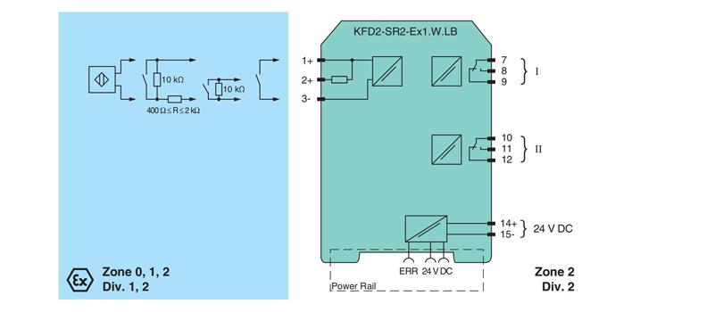
4. Configuration