1. General Introduction
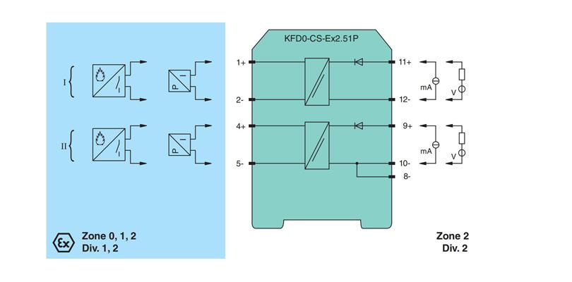
It transfers the analog input signal to the safe area as an isolated current value. Digital signals may be superimposed on the input signal in the hazardous or safe area and are transferred bi-directionally. If the HART communication resistance in the loop is too low, the internal resistance of 250 Ω between terminals 8, 9 and 11, 12 can be used. Test sockets for the connection of HART communicators are integrated into the terminals of the device
2. General Specification for KFD2-CRG2-EX1.D
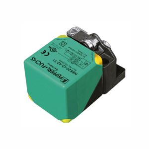
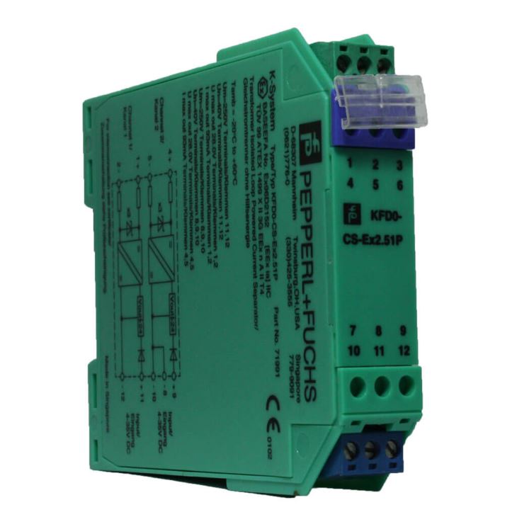
Model | KFD0-CS-Ex2.51P |
General specifications | |
Signal type | Analog input |
Functional safety related parameters | |
Safety Integrity Level (SIL) | SIL 2 |
Supply | |
Connection | Power Rail or terminals 23+, 24- |
Rated voltage Ur | 20 ... 35 V DC |
Rated current Ir | approx. 130 mA |
Ripple | within the supply tolerance |
Power dissipation | 2 W |
Power consumption | 2.5 W |
Interface | |
Programming interface | programming socket |
Input | |
Connection side | field side |
Connection | terminals1, 2, 3 |
Input I | |
Input signal | 0/4 ... 20 mA |
Available voltage | ≥ 15 V at 20 mA |
Open circuit voltage/short-circuit current | 24 V / 33 mA |
Line fault detection | breakage I < 0.2 mA; short-circuit I > 22 mA |
Input resistance | 45 Ω (terminals 2, 3) |
Output | |
Connection side | control side |
Connectio | output I: terminals 10, 11, 12 output II: terminals 16, 17, 18 output III: terminals 8+, 7- |
Output signal | 0 ... 20 mA or 4 ... 20 mA |
Output I, II | signal, relay |
Contact loading | 250 V AC / 2 A / cos φ ≥ 0.7 ; 40 DC / 2 A |
Mechanical life | 5 x 10⁷ switching cycles |
Output III | Signal, analog |
Current range | 0 ... 20 mA or 4 ... 20 mA |
Open loop voltage | ≤ 24 V DC |
Load | ≤ 650 Ω |
Fault signal | downscale I ≤ 3.6 mA, upscale I ≥ 21 mA (acc. NAMUR NE43) |
Energized/De-energized delay | 0 ... 250 s , adjustable |
Transfer characteristics | |
Deviation | at 20 °C (68 °F), 0/4 ... 20 mA ≤± 10 A incl. calibration, linearity, hysteresis, loads and supply voltage |
Input I | |
Accuracy | < 30 μA |
Influence of ambient temperature | 0.005 %/K (50 ppm) |
Reaction time | < 650 ms at bounce from 0 ... 20 mA at the input, 90 % of output full-scale value |
Rise time/fall time | 20 μs |
Settling time | 200 μs |
Galvanic isolation | |
Input/Other circuits | reinforced insulation according to IEC/EN 61010-1, rated insulation voltage 300 Vef |
Output I, II/other circuits | reinforced insulation according to IEC/EN 61010-1, rated insulation voltage 300 Veff |
Mutual output I, II, III | Mutual output I, II, III |
Indicators/settings | |
Display elements | LED display |
Control elements | Control panel |
Configuration | via operating buttons via PACTware |
Labeling | space for labeling at the front |
Directive conformity | |
Electromagnetic compatibility | |
Directive 2014/30/EU | EN 61326-1:2013 (industrial locations) |
Low voltage | |
Conformity | |
Electromagnetic compatibility | NE 21:2011 |
Degree of protection | IEC 60529:2001 |
Ambient conditions | |
Ambient temperature | -20 ... 60 °C (-4 ... 140 °F) |
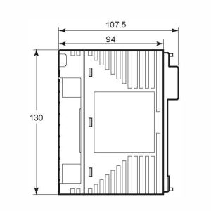
3. Assembly
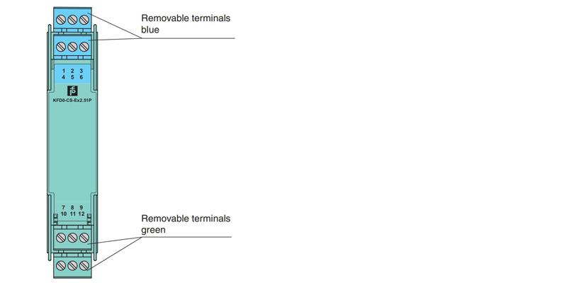
4. Connection