
1. General Introduction
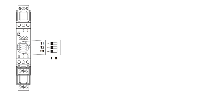
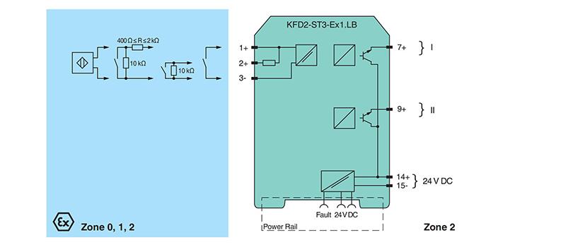
The proximity sensor or switch controls a form A normally open relay contact for the safe area load. The normal output state can be reversed using switches S1 and S2. Switch S3 is used to enable or disable line fault detection of the field circuit. During an error condition, relays revert to their de-energized ,state and LEDs indicate the fault according to NAMUR NE44. A unique collective error messaging feature is available when used with the Power Rail system. Due to its compact housing design and low heat dissipation,this device is useful for detecting positions, end stops, andswitching states in space-critical applications.
2. General Specification for KFD2-ST3-Ex1.LB
Model | KFD2-ST3-Ex1.LB |
General specifications | |
Signal type | Digital Input |
Functional safety related parameters | |
Safety Integrity Level (SIL) | SIL 2 |
Supply | |
Connection | Power Rail or terminals 14+, 15- |
Rated voltage Ur | 19 ... 30 V DC |
Ripple | ≤10 % |
Rated current Ir | 15 ... 10 mA + Iout |
Power dissipation | ≤800 mW including maximum power dissipation in the output |
Input | |
Connection side | field side |
Connection | terminals 1+, 2+, 3- |
Rated values | acc. to EN 60947-5-6 (NAMUR), see system description for electrical data |
Open circuit voltage/short-circuit current | approx. 10 V DC / approx. 8 mA |
Switching point/switching hysteresis | 1.2 ... 2.1 mA / approx. 0.2 mA |
Line fault detection | breakage I ≤0.1 mA , short-circuit I ≥6.5 mA |
Pulse/Pause ratio | ≥100 s / ≥100 s |
Output | |
Connection side | control side |
Connection | output I: terminal 7+ ; output II: terminal 9+ |
Rated voltage Un | 30 V DC |
Rated current In | 100 mA |
Response time | ≤200 s |
Signal level | 1-signal: (supply voltage) - 3 V max. for 100 mA 0-signal: blocked output (off-state current ≤10 A) |
Output I | signal ; Transistor |
Output II | signal or error message ; Transistor |
Transfer characteristics | |
Switching frequency | ≤5 kHz |
Indicators/settings | |
Display elements | LEDs |
Control elements | DIP-switch |
Directive conformity | |
Electromagnetic compatibility | |
Directive 2014/30/EU | EN 61326-1:2013 (industrial locations) |
Conformity | |
Electromagnetic compatibility | NE 21:2012 , EN 61326-3-2:2008 |
Degree of protection | IEC 60529:2001 |
Input | EN 60947-5-6:2000 |
Ambient conditions | |
Ambient temperature | -20 ... 60 °C (-4 ... 140 °F) |
3. Connection
4. Configuration