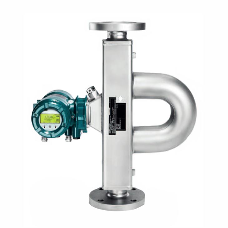
1. General introduction
Supreme Coriolis mass flow meter is for accurate flow applications, typical line sizes: DN15, DN25, DN40, DN50, DN65, DN80, DN100, DN125, 1/4”, 1/2”, 1”, 1 1/2”, 2”, 3”, 4”, 5”and maximum mass flow up to 170 t/h and volume up to 170 m3/h, delivers unsurpassed performance for demanding and critical applications with superior aeration handling and advanced diagnostic functionality.
2. Measuring range limits
Meter size | Normal Mass Flow | Maximum mass flow | Normal Volume flow | Max Volume flow | Normal Temperature | Max. Temperature | Density |
Supreme 34 | 3 t/h | 5 t/h | 3 m3/h | 5 m3/h | -50 to150℃ | -70 to 350℃ | 0 to 5 kg/l |
Supreme 36 | 10 t/h | 17 t/h | 10 m3/h | 17 m3/h | |||
Supreme 38 | 32 t/h | 50 t/h | 32 m3/h | 50 m3/h | 0 to 2 kg/l | ||
Supreme 39 | 100 t/h | 170 t/h | 100 m3/h | 170 m3/h |
3. Accuracy of liquids Measurement
Measured quantity | Accuracy for transmitters | ||
Essential | Ultimate | ||
Mass flow | Accuracy | 0.15 % of measured value | 0.1 % of measured value |
Repeatability | 0.08 % of measured value | 0.05 % of measured value | |
Volume flow | Accuracy | 0.43 % of measured value | 0.12 % of measured value |
Repeatability | 0.22 % of measured value | 0.06 % of measured value | |
Density | Accuracy | 4 g/l (0.25 lb/ft³) | 0.5 g/l (0.03 lb/ft³) |
Repeatability | 2 g/l (0.13 lb/ft³) | 0.3 g/l (0.02 lb/ft³) | |
Temperature | Accuracy | 0.5℃ (0.9℉) | 0.5℃ (0.9℉) |
4. Accuracy of gas Measurement
Measured quantity | Accuracy for transmitters | ||
Essential | Ultimate | ||
Mass flow | Accuracy | 0.75 % of measured value | 0.5 % of measured value |
Repeatability | 0.6 % of measured value | 0.4 % of measured value | |
Volume flow | Accuracy | 0.75 % of measured value | 0.5 % of measured value |
Repeatability | 0.6 % of measured value | 0.4 % of measured value | |
Temperature | Accuracy | 0.5℃ (0.9℉) | 0.5℃ (0.9℉) |
5. Model selection of Supreme 34
Main Code | Suffix Codes | Description | |||||||||||||
RC | Always RC | ||||||||||||||
Transmitter | E | Essential (base function) | |||||||||||||
U | Ultimate (high function) | ||||||||||||||
Sensor | S | Supreme | |||||||||||||
Meter size | 34 | Nominal mass flow : 3 t/h (110 lb/min), Maximum mass flow: 5 t/h (180 lb/min) | |||||||||||||
Material of wetted parts | S | Stainless steel 1.4404/316L | |||||||||||||
H | Ni alloy C-22/2.4602 | ||||||||||||||
Process connection size | 08 | ⅜" | |||||||||||||
15 | DN15, ½" | ||||||||||||||
20 | ¾" | ||||||||||||||
25 | DN25, 1" | ||||||||||||||
40 | DN40, 1½" | ||||||||||||||
50 | 2" | ||||||||||||||
Process connection type | BA1 | ASME flange class 150, suitable for ASME B16.5, raised face (RF) | |||||||||||||
BA2 | ASME flange class 300, suitable for ASME B16.5, raised face (RF) | ||||||||||||||
BA4 | ASME flange class 600, suitable for ASME B16.5, raised face (RF) | ||||||||||||||
CA4 | ASME flange class 600, suitable for ASME B16.5, ring joint (RJ) | ||||||||||||||
BD4 | EN flange PN 40, suitable for EN 1092-1 type B1, raised face (RF) | ||||||||||||||
ED4 | EN flange PN 40, suitable for EN 1092-1 type E, spigot | ||||||||||||||
FD4 | EN flange PN 40, suitable for EN 1092-1 type F, recess | ||||||||||||||
GD4 | EN flange PN 40, suitable for EN 1092-1 type D, groove | ||||||||||||||
BD6 | EN flange PN 100, suitable for EN 1092-1 type B1, raised face (RF) | ||||||||||||||
ED6 | EN flange PN 100, suitable for EN 1092-1 type E, spigot | ||||||||||||||
FD6 | EN flange PN 100, suitable for EN 1092-1 type F, recess | ||||||||||||||
GD6 | EN flange PN 100, suitable for EN 1092-1 type D, groove | ||||||||||||||
BJ1 | JIS flange 10K, JIS B 2220 | ||||||||||||||
BJ2 | JIS flange 20K, JIS B 2220 | ||||||||||||||
BP1 | JPI flange class 150 | ||||||||||||||
BP2 | JPI flange class 300 | ||||||||||||||
BP4 | JPI flange class 600 | ||||||||||||||
TG9 | Process connection with internal thread G | ||||||||||||||
TT9 | Process connection with internal thread NPT | ||||||||||||||
HS4 | Clamp process connection according to DIN 32676 series A | ||||||||||||||
HS8 | Clamp process connection according to DIN 32676 series C (Tri-Clamp) | ||||||||||||||
HS9 | Clamp process connection according to JIS/ISO 2852 | ||||||||||||||
Sensor housing 0material | 0 | Stainless steel 1.4301/304, 1.4404/316L | |||||||||||||
1 | Stainless steel 1.4404/316L | ||||||||||||||
Process fluid temperature range | 0 | Standard integrate: -50 to 150℃ (-58 to 302℉), remote type: -70 to 200 °C (-94 – 392 °F) | |||||||||||||
2 | Mid-range: -70 to 230℃ (-94 to 446℉) | ||||||||||||||
3 | High: 0 to 350℃ (32 to 662℉) | ||||||||||||||
Mass flow and density accuracy | E7 | Liquid: 0.2 % maximum mass flow deviation, 4 g/l density deviation | |||||||||||||
D7 | Liquid: 0.15 % maximum mass flow deviation, 4 g/l density deviation | ||||||||||||||
C6 | Liquid: 0.1 % maximum mass flow deviation, 3 g/l density deviation | ||||||||||||||
C3 | Liquid: 0.1 % maximum mass flow deviation, 1 g/l density deviation | ||||||||||||||
C2 | Liquid: 0.1 % maximum mass flow deviation, 0.5 g/l density deviation | ||||||||||||||
70 | Gas: 0.75% maximum mass flow deviation | ||||||||||||||
50 | Gas: 0.5% maximum mass flow deviation | ||||||||||||||
Design and housing | 0 | Integral type with "urethane-cured polyester powder coating" coated aluminum transmitter housing | |||||||||||||
2 | Integral type with "corrosion protection coating" coated aluminum transmitter housing | ||||||||||||||
A | Remote type with "urethane-cured polyester powder coating" coated aluminum transmitter housing and standard neck sensor | ||||||||||||||
B | Remote type with "urethane-cured polyester powder coating" coated aluminum transmitter housing and long neck sensor | ||||||||||||||
E | Remote type with "corrosion protection coating" coated aluminum transmitter housing and standard neck sensor | ||||||||||||||
F | Remote type with "corrosion protection coating" coated aluminum transmitter housing and long neck sensor | ||||||||||||||
J | Remote type stainless steel transmitter and standard neck sensor | ||||||||||||||
K | Remote type stainless steel transmitter and long neck sensor | ||||||||||||||
Ex approval | NN00 | None | |||||||||||||
KF21 | ATEX, explosion group IIC and IIIC | ||||||||||||||
KF22 | ATEX, explosion group IIB and IIIC | ||||||||||||||
SF21 | IECEx, explosion group IIC and IIIC | ||||||||||||||
SF22 | IECEx, explosion group IIB and IIIC | ||||||||||||||
GF21 | EAC Ex, explosion group IIC and IIIC | ||||||||||||||
GF22 | EAC Ex, explosion group IIB and IIIC | ||||||||||||||
FF11 | FM, groups A, B, C, D, E, F, G | ||||||||||||||
FF12 | FM, groups C, D, E, F, G | ||||||||||||||
UF21 | INMETRO, explosion group IIC and IIIC | ||||||||||||||
UF22 | INMETRO, explosion group IIB and IIIC | ||||||||||||||
NF21 | NEPSI, explosion group IIC and IIIC | ||||||||||||||
NF22 | NEPSI, explosion group IIB and IIIC | ||||||||||||||
PF21 | Korea Ex, explosion group IIC and IIIC | ||||||||||||||
PF22 | Korea Ex, explosion group IIB and IIIC | ||||||||||||||
Cable entries | 2 | ANSI ½" NPT | |||||||||||||
4 | ISO M20x1.5 | ||||||||||||||
Communication type and I/O | JA | active current output HART,1 passive pulse or status output | |||||||||||||
JB | 2 active current outputs one with HART,2 passive pulse or status outputs | ||||||||||||||
JC | 2 active current outputs one with HART,1 passive pulse or status output,1 voltage-free status input | ||||||||||||||
JD | 1 active current output HART,2 passive pulse or status outputs,1 passive status output | ||||||||||||||
JE | 1 active current output HART,2 passive pulse or status outputs,1 voltage-free status input | ||||||||||||||
JF | 1 active current output HART,1 passive pulse or status output,1 active pulse or status output with pull-up resistor,1 voltage-free status input | ||||||||||||||
JG | 1 active current output HART,1 passive pulse or status output,1 active pulse or status output,1 voltage-free status input | ||||||||||||||
JH | 1 active current output HART,1 passive pulse or status output,1 passive current output,1 active current input | ||||||||||||||
JJ | 1 active current output HART,2 passive pulse or status outputs,1 active current input | ||||||||||||||
JK | 1 active current output HART,1 passive pulse or status output,1 voltage-free status input,1 active current input | ||||||||||||||
JL | 1 active current output HART,1 passive pulse or status output,1 passive current output,1 passive current input | ||||||||||||||
JM | 1 active current output HART, 2 passive pulse or status outputs,1 passive current input | ||||||||||||||
JN | 1 active current output HART,1 passive pulse or status output,1 voltage-free status input,1 passive current input | ||||||||||||||
JP | 2 passive current outputs one with HART,1 passive pulse or status output | ||||||||||||||
JQ | 2 passive current outputs one with HART,2 passive pulse or status outputs | ||||||||||||||
JR | 2 passive current outputs one with HART,1 passive NAMUR pulse or status output | ||||||||||||||
JS | 2 passive current outputs one with HART,2 passive NAMUR pulse or status outputs | ||||||||||||||
M0 | Modbus output,1 passive pulse or status output | ||||||||||||||
M2 | Modbus output,1 passive pulse or status output,1 active current input | ||||||||||||||
M3 | Modbus output, 2 passive pulse or status outputs | ||||||||||||||
M4 | Modbus output,1 passive pulse or status output, 1 active pulse or status output | ||||||||||||||
M5 | Modbus output, 1 passive pulse or status output, 1 active pulse or status output with pull-up resistor | ||||||||||||||
M6 | Modbus output,1 passive pulse or status output, 1 active current output | ||||||||||||||
M7 | Modbus output, 1 passive pulse or status output, 1 passive current input | ||||||||||||||
Display | 0 | No display | |||||||||||||
1 | With display | ||||||||||||||
Optional codes | /Optional codes | ||||||||||||||
6. Model selection of Supreme 36
Main Code | Suffix Codes | Description | |||||||||||||
RC | Always RC | ||||||||||||||
Transmitter | E | Essential (base function) | |||||||||||||
U | Ultimate (high function) | ||||||||||||||
Sensor | S | Supreme | |||||||||||||
Meter size | 36 | Nominal mass flow : 10 t/h (370 lb/min), Maximum mass flow: 17 t/h (620 lb/min) | |||||||||||||
Material of wetted parts | S | Stainless steel 1.4404/316L | |||||||||||||
H | Ni alloy C-22/2.4602 | ||||||||||||||
Process connection size | 25 | DN25, 1" | |||||||||||||
40 | DN40, 1½" | ||||||||||||||
50 | 2" | ||||||||||||||
Process connection type | BA1 | ASME flange class 150, suitable for ASME B16.5, raised face (RF) | |||||||||||||
BA2 | ASME flange class 300, suitable for ASME B16.5, raised face (RF) | ||||||||||||||
BA4 | ASME flange class 600, suitable for ASME B16.5, raised face (RF) | ||||||||||||||
CA4 | ASME flange class 600, suitable for ASME B16.5, ring joint (RJ) | ||||||||||||||
BD4 | EN flange PN 40, suitable for EN 1092-1 type B1, raised face (RF) | ||||||||||||||
ED4 | EN flange PN 40, suitable for EN 1092-1 type E, spigot | ||||||||||||||
FD4 | EN flange PN 40, suitable for EN 1092-1 type F, recess | ||||||||||||||
GD4 | EN flange PN 40, suitable for EN 1092-1 type D, groove | ||||||||||||||
BD6 | EN flange PN 100, suitable for EN 1092-1 type B1, raised face (RF) | ||||||||||||||
ED6 | EN flange PN 100, suitable for EN 1092-1 type E, spigot | ||||||||||||||
FD6 | EN flange PN 100, suitable for EN 1092-1 type F, recess | ||||||||||||||
GD6 | EN flange PN 100, suitable for EN 1092-1 type D, groove | ||||||||||||||
BJ1 | JIS flange 10K, JIS B 2220 | ||||||||||||||
BJ2 | JIS flange 20K, JIS B 2220 | ||||||||||||||
BP1 | JPI flange class 150 | ||||||||||||||
BP2 | JPI flange class 300 | ||||||||||||||
BP4 | JPI flange class 600 | ||||||||||||||
TG9 | Process connection with internal thread G | ||||||||||||||
TT9 | Process connection with internal thread NPT | ||||||||||||||
HS4 | Clamp process connection according to DIN 32676 series A | ||||||||||||||
HS8 | Clamp process connection according to DIN 32676 series C (Tri-Clamp) | ||||||||||||||
HS9 | Clamp process connection according to JIS/ISO 2852 | ||||||||||||||
Sensor housing 0material | 0 | Stainless steel 1.4301/304, 1.4404/316L | |||||||||||||
1 | Stainless steel 1.4404/316L | ||||||||||||||
Process fluid temperature range | 0 | Standard integrate: -50 to 150℃ (-58 to 302℉), remote type: -70 to 200 °C (-94 – 392 °F) | |||||||||||||
2 | Mid-range: -70 to 230℃ (-94 to 446℉) | ||||||||||||||
3 | High: 0 to 350℃ (32 to 662℉) | ||||||||||||||
Mass flow and density accuracy | E7 | Liquid: 0.2 % maximum mass flow deviation, 4 g/l density deviation | |||||||||||||
D7 | Liquid: 0.15 % maximum mass flow deviation, 4 g/l density deviation | ||||||||||||||
C6 | Liquid: 0.1 % maximum mass flow deviation, 3 g/l density deviation | ||||||||||||||
C3 | Liquid: 0.1 % maximum mass flow deviation, 1 g/l density deviation | ||||||||||||||
C2 | Liquid: 0.1 % maximum mass flow deviation, 0.5 g/l density deviation | ||||||||||||||
70 | Gas: 0.75% maximum mass flow deviation | ||||||||||||||
50 | Gas: 0.5% maximum mass flow deviation | ||||||||||||||
Design and housing | 0 | Integral type with "urethane-cured polyester powder coating" coated aluminum transmitter housing | |||||||||||||
2 | Integral type with "corrosion protection coating" coated aluminum transmitter housing | ||||||||||||||
A | Remote type with "urethane-cured polyester powder coating" coated aluminum transmitter housing and standard neck sensor | ||||||||||||||
B | Remote type with "urethane-cured polyester powder coating" coated aluminum transmitter housing and long neck sensor | ||||||||||||||
E | Remote type with "corrosion protection coating" coated aluminum transmitter housing and standard neck sensor | ||||||||||||||
F | Remote type with "corrosion protection coating" coated aluminum transmitter housing and long neck sensor | ||||||||||||||
J | Remote type stainless steel transmitter and standard neck sensor | ||||||||||||||
K | Remote type stainless steel transmitter and long neck sensor | ||||||||||||||
Ex approval | NN00 | None | |||||||||||||
KF21 | ATEX, explosion group IIC and IIIC | ||||||||||||||
KF22 | ATEX, explosion group IIB and IIIC | ||||||||||||||
SF21 | IECEx, explosion group IIC and IIIC | ||||||||||||||
SF22 | IECEx, explosion group IIB and IIIC | ||||||||||||||
GF21 | EAC Ex, explosion group IIC and IIIC | ||||||||||||||
GF22 | EAC Ex, explosion group IIB and IIIC | ||||||||||||||
FF11 | FM, groups A, B, C, D, E, F, G | ||||||||||||||
FF12 | FM, groups C, D, E, F, G | ||||||||||||||
UF21 | INMETRO, explosion group IIC and IIIC | ||||||||||||||
UF22 | INMETRO, explosion group IIB and IIIC | ||||||||||||||
NF21 | NEPSI, explosion group IIC and IIIC | ||||||||||||||
NF22 | NEPSI, explosion group IIB and IIIC | ||||||||||||||
PF21 | Korea Ex, explosion group IIC and IIIC | ||||||||||||||
PF22 | Korea Ex, explosion group IIB and IIIC | ||||||||||||||
Cable entries | 2 | ANSI ½" NPT | |||||||||||||
4 | ISO M20x1.5 | ||||||||||||||
Communication type and I/O | JA | active current output HART,1 passive pulse or status output | |||||||||||||
JB | 2 active current outputs one with HART,2 passive pulse or status outputs | ||||||||||||||
JC | 2 active current outputs one with HART,1 passive pulse or status output,1 voltage-free status input | ||||||||||||||
JD | 1 active current output HART,2 passive pulse or status outputs,1 passive status output | ||||||||||||||
JE | 1 active current output HART,2 passive pulse or status outputs,1 voltage-free status input | ||||||||||||||
JF | 1 active current output HART,1 passive pulse or status output,1 active pulse or status output with pull-up resistor,1 voltage-free status input | ||||||||||||||
JG | 1 active current output HART,1 passive pulse or status output,1 active pulse or status output,1 voltage-free status input | ||||||||||||||
JH | 1 active current output HART,1 passive pulse or status output,1 passive current output,1 active current input | ||||||||||||||
JJ | 1 active current output HART,2 passive pulse or status outputs,1 active current input | ||||||||||||||
JK | 1 active current output HART,1 passive pulse or status output,1 voltage-free status input,1 active current input | ||||||||||||||
JL | 1 active current output HART,1 passive pulse or status output,1 passive current output,1 passive current input | ||||||||||||||
JM | 1 active current output HART, 2 passive pulse or status outputs,1 passive current input | ||||||||||||||
JN | 1 active current output HART,1 passive pulse or status output,1 voltage-free status input,1 passive current input | ||||||||||||||
JP | 2 passive current outputs one with HART,1 passive pulse or status output | ||||||||||||||
JQ | 2 passive current outputs one with HART,2 passive pulse or status outputs | ||||||||||||||
JR | 2 passive current outputs one with HART,1 passive NAMUR pulse or status output | ||||||||||||||
JS | 2 passive current outputs one with HART,2 passive NAMUR pulse or status outputs | ||||||||||||||
M0 | Modbus output,1 passive pulse or status output | ||||||||||||||
M2 | Modbus output,1 passive pulse or status output,1 active current input | ||||||||||||||
M3 | Modbus output, 2 passive pulse or status outputs | ||||||||||||||
M4 | Modbus output,1 passive pulse or status output, 1 active pulse or status output | ||||||||||||||
M5 | Modbus output, 1 passive pulse or status output, 1 active pulse or status output with pull-up resistor | ||||||||||||||
M6 | Modbus output,1 passive pulse or status output, 1 active current output | ||||||||||||||
M7 | Modbus output, 1 passive pulse or status output, 1 passive current input | ||||||||||||||
Display | 0 | No display | |||||||||||||
1 | With display | ||||||||||||||
Optional codes | /Optional codes | ||||||||||||||
7. Model selection of Supreme 38
Main Code | Suffix Codes | Description | |||||||||||||
RC | Always RC | ||||||||||||||
Transmitter | E | Essential (base function) | |||||||||||||
U | Ultimate (high function) | ||||||||||||||
Sensor | S | Supreme | |||||||||||||
Meter size | 38 | Nominal mass flow : 32 t/h (1200 lb/min), Maximum mass flow: 50 t/h (1800 lb/min) | |||||||||||||
Material of wetted parts | S | Stainless steel 1.4404/316L | |||||||||||||
H | Ni alloy C-22/2.4602 | ||||||||||||||
Process connection size | 40 | DN40, 1½" | |||||||||||||
50 | 2" | ||||||||||||||
65 | DN65, 2½" | ||||||||||||||
80 | DN80, 3" | ||||||||||||||
Process connection type | BA1 | ASME flange class 150, suitable for ASME B16.5, raised face (RF) | |||||||||||||
BA2 | ASME flange class 300, suitable for ASME B16.5, raised face (RF) | ||||||||||||||
BA4 | ASME flange class 600, suitable for ASME B16.5, raised face (RF) | ||||||||||||||
CA4 | ASME flange class 600, suitable for ASME B16.5, ring joint (RJ) | ||||||||||||||
BD4 | EN flange PN 40, suitable for EN 1092-1 type B1, raised face (RF) | ||||||||||||||
ED4 | EN flange PN 40, suitable for EN 1092-1 type E, spigot | ||||||||||||||
FD4 | EN flange PN 40, suitable for EN 1092-1 type F, recess | ||||||||||||||
GD4 | EN flange PN 40, suitable for EN 1092-1 type D, groove | ||||||||||||||
BD6 | EN flange PN 100, suitable for EN 1092-1 type B1, raised face (RF) | ||||||||||||||
ED6 | EN flange PN 100, suitable for EN 1092-1 type E, spigot | ||||||||||||||
FD6 | EN flange PN 100, suitable for EN 1092-1 type F, recess | ||||||||||||||
GD6 | EN flange PN 100, suitable for EN 1092-1 type D, groove | ||||||||||||||
BJ1 | JIS flange 10K, JIS B 2220 | ||||||||||||||
BJ2 | JIS flange 20K, JIS B 2220 | ||||||||||||||
BP1 | JPI flange class 150 | ||||||||||||||
BP2 | JPI flange class 300 | ||||||||||||||
BP4 | JPI flange class 600 | ||||||||||||||
TG9 | Process connection with internal thread G | ||||||||||||||
TT9 | Process connection with internal thread NPT | ||||||||||||||
HS4 | Clamp process connection according to DIN 32676 series A | ||||||||||||||
HS8 | Clamp process connection according to DIN 32676 series C (Tri-Clamp) | ||||||||||||||
HS9 | Clamp process connection according to JIS/ISO 2852 | ||||||||||||||
Sensor housing 0material | 0 | Stainless steel 1.4301/304, 1.4404/316L | |||||||||||||
1 | Stainless steel 1.4404/316L | ||||||||||||||
Process fluid temperature range | 0 | Standard integrate: -50 to 150℃ (-58 to 302℉), remote type: -70 to 200 °C (-94 – 392 °F) | |||||||||||||
2 | Mid-range: -70 to 230℃ (-94 to 446℉) | ||||||||||||||
3 | High: 0 to 350℃ (32 to 662℉) | ||||||||||||||
Mass flow and density accuracy | E7 | Liquid: 0.2 % maximum mass flow deviation, 4 g/l density deviation | |||||||||||||
D7 | Liquid: 0.15 % maximum mass flow deviation, 4 g/l density deviation | ||||||||||||||
C6 | Liquid: 0.1 % maximum mass flow deviation, 3 g/l density deviation | ||||||||||||||
C3 | Liquid: 0.1 % maximum mass flow deviation, 1 g/l density deviation | ||||||||||||||
C2 | Liquid: 0.1 % maximum mass flow deviation, 0.5 g/l density deviation | ||||||||||||||
70 | Gas: 0.75% maximum mass flow deviation | ||||||||||||||
50 | Gas: 0.5% maximum mass flow deviation | ||||||||||||||
Design and housing | 0 | Integral type with "urethane-cured polyester powder coating" coated aluminum transmitter housing | |||||||||||||
2 | Integral type with "corrosion protection coating" coated aluminum transmitter housing | ||||||||||||||
A | Remote type with "urethane-cured polyester powder coating" coated aluminum transmitter housing and standard neck sensor | ||||||||||||||
B | Remote type with "urethane-cured polyester powder coating" coated aluminum transmitter housing and long neck sensor | ||||||||||||||
E | Remote type with "corrosion protection coating" coated aluminum transmitter housing and standard neck sensor | ||||||||||||||
F | Remote type with "corrosion protection coating" coated aluminum transmitter housing and long neck sensor | ||||||||||||||
J | Remote type stainless steel transmitter and standard neck sensor | ||||||||||||||
K | Remote type stainless steel transmitter and long neck sensor | ||||||||||||||
Ex approval | NN00 | None | |||||||||||||
KF21 | ATEX, explosion group IIC and IIIC | ||||||||||||||
KF22 | ATEX, explosion group IIB and IIIC | ||||||||||||||
SF21 | IECEx, explosion group IIC and IIIC | ||||||||||||||
SF22 | IECEx, explosion group IIB and IIIC | ||||||||||||||
GF21 | EAC Ex, explosion group IIC and IIIC | ||||||||||||||
GF22 | EAC Ex, explosion group IIB and IIIC | ||||||||||||||
FF11 | FM, groups A, B, C, D, E, F, G | ||||||||||||||
FF12 | FM, groups C, D, E, F, G | ||||||||||||||
UF21 | INMETRO, explosion group IIC and IIIC | ||||||||||||||
UF22 | INMETRO, explosion group IIB and IIIC | ||||||||||||||
NF21 | NEPSI, explosion group IIC and IIIC | ||||||||||||||
NF22 | NEPSI, explosion group IIB and IIIC | ||||||||||||||
PF21 | Korea Ex, explosion group IIC and IIIC | ||||||||||||||
PF22 | Korea Ex, explosion group IIB and IIIC | ||||||||||||||
Cable entries | 2 | ANSI ½" NPT | |||||||||||||
4 | ISO M20x1.5 | ||||||||||||||
Communication type and I/O | JA | active current output HART,1 passive pulse or status output | |||||||||||||
JB | 2 active current outputs one with HART,2 passive pulse or status outputs | ||||||||||||||
JC | 2 active current outputs one with HART,1 passive pulse or status output,1 voltage-free status input | ||||||||||||||
JD | 1 active current output HART,2 passive pulse or status outputs,1 passive status output | ||||||||||||||
JE | 1 active current output HART,2 passive pulse or status outputs,1 voltage-free status input | ||||||||||||||
JF | 1 active current output HART,1 passive pulse or status output,1 active pulse or status output with pull-up resistor,1 voltage-free status input | ||||||||||||||
JG | 1 active current output HART,1 passive pulse or status output,1 active pulse or status output,1 voltage-free status input | ||||||||||||||
JH | 1 active current output HART,1 passive pulse or status output,1 passive current output,1 active current input | ||||||||||||||
JJ | 1 active current output HART,2 passive pulse or status outputs,1 active current input | ||||||||||||||
JK | 1 active current output HART,1 passive pulse or status output,1 voltage-free status input,1 active current input | ||||||||||||||
JL | 1 active current output HART,1 passive pulse or status output,1 passive current output,1 passive current input | ||||||||||||||
JM | 1 active current output HART, 2 passive pulse or status outputs,1 passive current input | ||||||||||||||
JN | 1 active current output HART,1 passive pulse or status output,1 voltage-free status input,1 passive current input | ||||||||||||||
JP | 2 passive current outputs one with HART,1 passive pulse or status output | ||||||||||||||
JQ | 2 passive current outputs one with HART,2 passive pulse or status outputs | ||||||||||||||
JR | 2 passive current outputs one with HART,1 passive NAMUR pulse or status output | ||||||||||||||
JS | 2 passive current outputs one with HART,2 passive NAMUR pulse or status outputs | ||||||||||||||
M0 | Modbus output,1 passive pulse or status output | ||||||||||||||
M2 | Modbus output,1 passive pulse or status output,1 active current input | ||||||||||||||
M3 | Modbus output, 2 passive pulse or status outputs | ||||||||||||||
M4 | Modbus output,1 passive pulse or status output, 1 active pulse or status output | ||||||||||||||
M5 | Modbus output, 1 passive pulse or status output, 1 active pulse or status output with pull-up resistor | ||||||||||||||
M6 | Modbus output,1 passive pulse or status output, 1 active current output | ||||||||||||||
M7 | Modbus output, 1 passive pulse or status output, 1 passive current input | ||||||||||||||
Display | 0 | No display | |||||||||||||
1 | With display | ||||||||||||||
Optional codes | /Optional codes | ||||||||||||||
8. Model selection of Supreme 39
Main Code | Suffix Codes | Description | |||||||||||||
RC | Always RC | ||||||||||||||
Transmitter | E | Essential (base function) | |||||||||||||
U | Ultimate (high function) | ||||||||||||||
Sensor | S | Supreme | |||||||||||||
Meter size | 39 | Nominal mass flow : 32 t/h (1200 lb/min), Maximum mass flow: 50 t/h (1800 lb/min) | |||||||||||||
Material of wetted parts | S | Stainless steel 1.4404/316L | |||||||||||||
H | Ni alloy C-22/2.4602 | ||||||||||||||
Process connection size | 80 | DN80, 3" | |||||||||||||
1H | DN100, 4" | ||||||||||||||
1Q | DN125, 5" | ||||||||||||||
Process connection type | BA1 | ASME flange class 150, suitable for ASME B16.5, raised face (RF) | |||||||||||||
BA2 | ASME flange class 300, suitable for ASME B16.5, raised face (RF) | ||||||||||||||
BA4 | ASME flange class 600, suitable for ASME B16.5, raised face (RF) | ||||||||||||||
CA4 | ASME flange class 600, suitable for ASME B16.5, ring joint (RJ) | ||||||||||||||
BD4 | EN flange PN 40, suitable for EN 1092-1 type B1, raised face (RF) | ||||||||||||||
ED4 | EN flange PN 40, suitable for EN 1092-1 type E, spigot | ||||||||||||||
FD4 | EN flange PN 40, suitable for EN 1092-1 type F, recess | ||||||||||||||
GD4 | EN flange PN 40, suitable for EN 1092-1 type D, groove | ||||||||||||||
BD6 | EN flange PN 100, suitable for EN 1092-1 type B1, raised face (RF) | ||||||||||||||
ED6 | EN flange PN 100, suitable for EN 1092-1 type E, spigot | ||||||||||||||
FD6 | EN flange PN 100, suitable for EN 1092-1 type F, recess | ||||||||||||||
GD6 | EN flange PN 100, suitable for EN 1092-1 type D, groove | ||||||||||||||
BJ1 | JIS flange 10K, JIS B 2220 | ||||||||||||||
BJ2 | JIS flange 20K, JIS B 2220 | ||||||||||||||
BP1 | JPI flange class 150 | ||||||||||||||
BP2 | JPI flange class 300 | ||||||||||||||
BP4 | JPI flange class 600 | ||||||||||||||
TG9 | Process connection with internal thread G | ||||||||||||||
TT9 | Process connection with internal thread NPT | ||||||||||||||
HS4 | Clamp process connection according to DIN 32676 series A | ||||||||||||||
HS8 | Clamp process connection according to DIN 32676 series C (Tri-Clamp) | ||||||||||||||
HS9 | Clamp process connection according to JIS/ISO 2852 | ||||||||||||||
Sensor housing 0material | 0 | Stainless steel 1.4301/304, 1.4404/316L | |||||||||||||
1 | Stainless steel 1.4404/316L | ||||||||||||||
Process fluid temperature range | 0 | Standard integrate: -50 to 150℃ (-58 to 302℉), remote type: -70 to 200 °C (-94 – 392 °F) | |||||||||||||
2 | Mid-range: -70 to 230℃ (-94 to 446℉) | ||||||||||||||
3 | High: 0 to 350℃ (32 to 662℉) | ||||||||||||||
Mass flow and density accuracy | E7 | Liquid: 0.2 % maximum mass flow deviation, 4 g/l density deviation | |||||||||||||
D7 | Liquid: 0.15 % maximum mass flow deviation, 4 g/l density deviation | ||||||||||||||
C6 | Liquid: 0.1 % maximum mass flow deviation, 3 g/l density deviation | ||||||||||||||
C3 | Liquid: 0.1 % maximum mass flow deviation, 1 g/l density deviation | ||||||||||||||
C2 | Liquid: 0.1 % maximum mass flow deviation, 0.5 g/l density deviation | ||||||||||||||
70 | Gas: 0.75% maximum mass flow deviation | ||||||||||||||
50 | Gas: 0.5% maximum mass flow deviation | ||||||||||||||
Design and housing | 0 | Integral type with "urethane-cured polyester powder coating" coated aluminum transmitter housing | |||||||||||||
2 | Integral type with "corrosion protection coating" coated aluminum transmitter housing | ||||||||||||||
A | Remote type with "urethane-cured polyester powder coating" coated aluminum transmitter housing and standard neck sensor | ||||||||||||||
B | Remote type with "urethane-cured polyester powder coating" coated aluminum transmitter housing and long neck sensor | ||||||||||||||
E | Remote type with "corrosion protection coating" coated aluminum transmitter housing and standard neck sensor | ||||||||||||||
F | Remote type with "corrosion protection coating" coated aluminum transmitter housing and long neck sensor | ||||||||||||||
J | Remote type stainless steel transmitter and standard neck sensor | ||||||||||||||
K | Remote type stainless steel transmitter and long neck sensor | ||||||||||||||
Ex approval | NN00 | None | |||||||||||||
KF21 | ATEX, explosion group IIC and IIIC | ||||||||||||||
KF22 | ATEX, explosion group IIB and IIIC | ||||||||||||||
SF21 | IECEx, explosion group IIC and IIIC | ||||||||||||||
SF22 | IECEx, explosion group IIB and IIIC | ||||||||||||||
GF21 | EAC Ex, explosion group IIC and IIIC | ||||||||||||||
GF22 | EAC Ex, explosion group IIB and IIIC | ||||||||||||||
FF11 | FM, groups A, B, C, D, E, F, G | ||||||||||||||
FF12 | FM, groups C, D, E, F, G | ||||||||||||||
UF21 | INMETRO, explosion group IIC and IIIC | ||||||||||||||
UF22 | INMETRO, explosion group IIB and IIIC | ||||||||||||||
NF21 | NEPSI, explosion group IIC and IIIC | ||||||||||||||
NF22 | NEPSI, explosion group IIB and IIIC | ||||||||||||||
PF21 | Korea Ex, explosion group IIC and IIIC | ||||||||||||||
PF22 | Korea Ex, explosion group IIB and IIIC | ||||||||||||||
Cable entries | 2 | ANSI ½" NPT | |||||||||||||
4 | ISO M20x1.5 | ||||||||||||||
Communication type and I/O | JA | active current output HART,1 passive pulse or status output | |||||||||||||
JB | 2 active current outputs one with HART,2 passive pulse or status outputs | ||||||||||||||
JC | 2 active current outputs one with HART,1 passive pulse or status output,1 voltage-free status input | ||||||||||||||
JD | 1 active current output HART,2 passive pulse or status outputs,1 passive status output | ||||||||||||||
JE | 1 active current output HART,2 passive pulse or status outputs,1 voltage-free status input | ||||||||||||||
JF | 1 active current output HART,1 passive pulse or status output,1 active pulse or status output with pull-up resistor,1 voltage-free status input | ||||||||||||||
JG | 1 active current output HART,1 passive pulse or status output,1 active pulse or status output,1 voltage-free status input | ||||||||||||||
JH | 1 active current output HART,1 passive pulse or status output,1 passive current output,1 active current input | ||||||||||||||
JJ | 1 active current output HART,2 passive pulse or status outputs,1 active current input | ||||||||||||||
JK | 1 active current output HART,1 passive pulse or status output,1 voltage-free status input,1 active current input | ||||||||||||||
JL | 1 active current output HART,1 passive pulse or status output,1 passive current output,1 passive current input | ||||||||||||||
JM | 1 active current output HART, 2 passive pulse or status outputs,1 passive current input | ||||||||||||||
JN | 1 active current output HART,1 passive pulse or status output,1 voltage-free status input,1 passive current input | ||||||||||||||
JP | 2 passive current outputs one with HART,1 passive pulse or status output | ||||||||||||||
JQ | 2 passive current outputs one with HART,2 passive pulse or status outputs | ||||||||||||||
JR | 2 passive current outputs one with HART,1 passive NAMUR pulse or status output | ||||||||||||||
JS | 2 passive current outputs one with HART,2 passive NAMUR pulse or status outputs | ||||||||||||||
M0 | Modbus output,1 passive pulse or status output | ||||||||||||||
M2 | Modbus output,1 passive pulse or status output,1 active current input | ||||||||||||||
M3 | Modbus output, 2 passive pulse or status outputs | ||||||||||||||
M4 | Modbus output,1 passive pulse or status output, 1 active pulse or status output | ||||||||||||||
M5 | Modbus output, 1 passive pulse or status output, 1 active pulse or status output with pull-up resistor | ||||||||||||||
M6 | Modbus output,1 passive pulse or status output, 1 active current output | ||||||||||||||
M7 | Modbus output, 1 passive pulse or status output, 1 passive current input | ||||||||||||||
Display | 0 | No display | |||||||||||||
1 | With display | ||||||||||||||
Optional codes | /Optional codes | ||||||||||||||
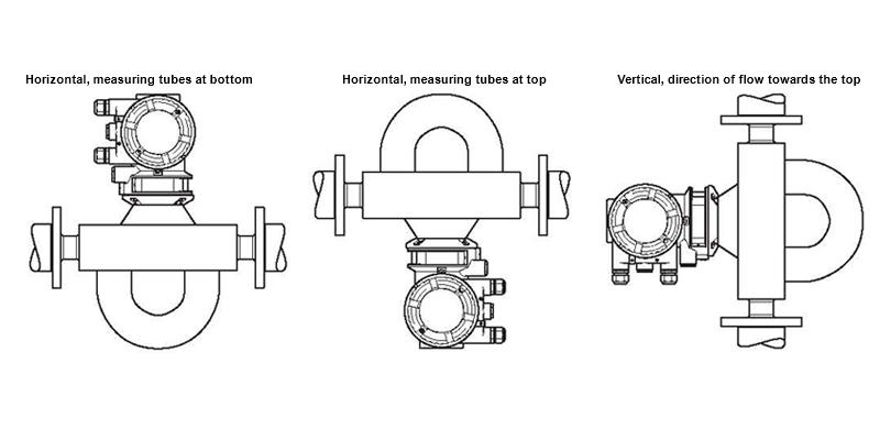
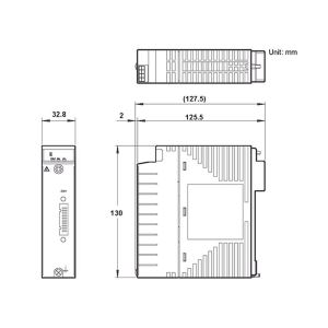
9. Location and position of installation